United States Power Grid System
Before we dive into the specific journey of an electron from a power plant to your light switch, we have to look at the “Big Picture.”
The U.S. power grid isn’t actually one single grid—it is a massive, complex machine made of three nearly independent parts that operate like a giant synchronized orchestra.
As of 2024 there were roughly 14,000 power generating plants in the USA (according to EIA.gov) with a capacity of 1.32 x 10¹² watts (i.e. 1.32 terawatts) of electric power capacity
Picture: USA Electric Power Grids and Transmission Planning Regions and Planning Groups (RTOs/ISOs/Other)
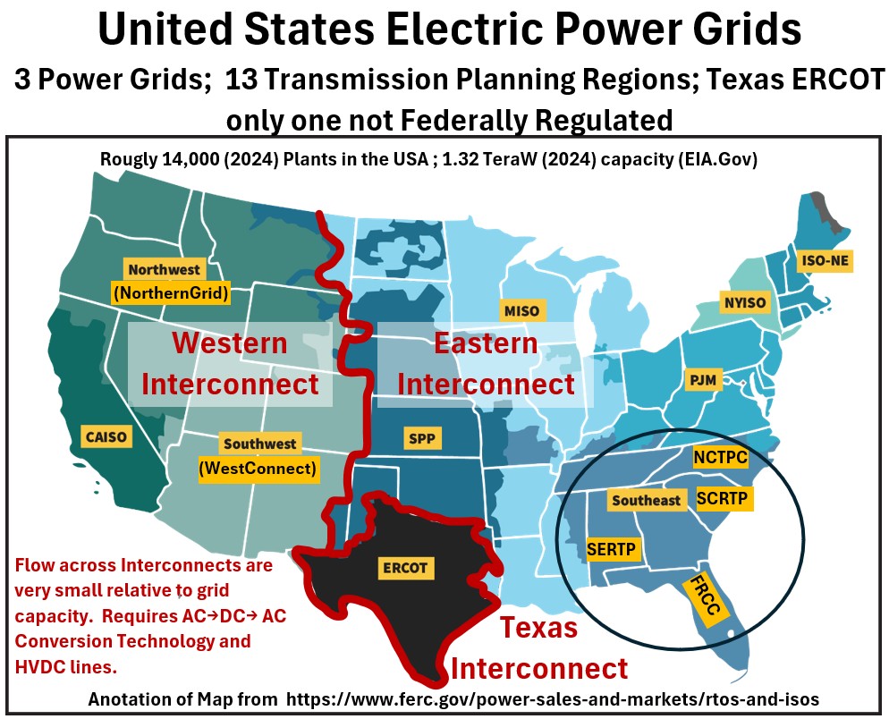
The Physical Layer: The Three “Islands”
Every generator in each of the three regions spin in perfect synchronization at .
- The Eastern Interconnection: The largest of the three. It covers everything from the foot of the Rockies to the Atlantic, including most of Canada (except Quebec).
- The Western Interconnection: This covers the Rockies to the Pacific, plus Western Canada and Baja California, Mexico.
- ERCOT (Texas Interconnection): The “Lone Star” island. It stays almost entirely within Texas borders to avoid federal regulation (no interstate commerce means no Federal involvement)
Flows Across Interconnects Requires Special Technology
Because these three regions are not in sync, you can’t just plug an AC wire from New Mexico (West) into Texas (ERCOT). The frequencies would clash instantly.
- The Solution: We use High Voltage Direct Current Lines (HVDC)
- How they work: They take the AC power from one grid, strip it down to Direct Current (DC) via rectification, and then “re-pulse” it back into AC via inversion at the exact timing of the second grid.
- Capacity is limited: They can only carry about 1% of what a grid like Texas (for example) actually needs in a crisis.
The Management Layer: RTOs/ISOs and Similar Organization
While the physical grid is the “hardware,” the Regional Transmission Organizations (RTOs) / Independent System Operators (ISOs) are the “operating system.”
They don’t usually own the wires—they run the markets and manage the systems.
There are 6 major organized markets (RTOs/ISOs) regulated by FERC (Federal Energy Regulatory Commission)
- PJM: The biggest (Mid-Atlantic).
- MISO: The Midwest.
- ISO-NE: New England.
- NYISO: New York.
- CAISO: California.
- SPP: Southwest Power Pool (The Central US).
The Texas market (most of it but not all of it) is not regulated by FERC.
Its managed by the Electric Reliability Council of Texas and since all the commerce occurs inside Texas, it is not regulated by FERC.
- ERCOT: Texas.
There are other organizations that exist as less structured assemblies
Southeast, Northwest, Southwest assemblies: In these areas, there is no central market.
The Texas Grid
ERCOT is 90% of Texas, but it is not the whole state.
- The West (El Paso): Part of the Western Interconnection. They are synced with Vegas and LA.
- The Panhandle (Amarillo/Upper Panhandle): Historically part of the Eastern Interconnection (via SPP).
- The East (Beaumont/Orange/The Piney Woods): Part of the Eastern Interconnection (via Entergy/MISO). If the lights go out in Houston, Beaumont might still be fine because they are plugged into the rest of the East Coast.
The Texas freeze, known as Winter Storm Uri, happened from February 11–20, 2021.
- During the worst of the crisis, ERCOT had a generation deficit of roughly 20,000 MW (20 GW).
- That was the “hole” that needed to be filled to keep the lights on.
- The HVDDC Ties to other grids had a total capacity of only about 1,220 MW.
- Even if they were running at 100% capacity—which they weren’t, because some neighbors were also struggling—they could have only filled about 6% of the 20,000 MW hole.
- The “Same Boat” Reality: The Eastern Interconnection (SPP and MISO) was also hitting record-breaking cold at the exact same time.
- They were forced to initiate their own rolling blackouts in states like Kansas and Oklahoma. You can’t import power from a neighbor whose own house is also on fire.
- If Texas had been a “fully synced” AC part of the Eastern Grid, the massive frequency drop in Texas might have actually dragged the neighboring states down with it, potentially causing a multi-state cascading collapse rather than just a local one.
The Nuance: Where It Could Have Helped
The only valid part of the interconnection argument is that MISO (which has much beefier lines connecting it to the East Coast) was able to import about 13,000 MW from the East to stabilize its own system.
However, for Texas to have benefited from that, they would have needed billions of dollars in massive DC lines built decades in advance—not just a simple “plug in” to the immediate neighbors who were also freezing.
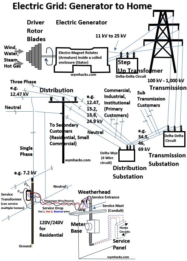
From the Power Plant to Your Home
So in the last section we’ve seen that, across the USA, there are 1000s of power plants, each supplying power to numerous power users in its region.
It’s time to zoom down and look at a single hypothetical power plant and describe how that alternating electric current gets to your house.
Getting electricity from a far away power plant (perhaps 100s of miles away) to your home AC unit or TV is basically an exercise in stepping up and stepping down voltage to balance efficiency with safety.
As we discuss the journey your power takes , please refer to these simplified sketches showing how power cascades down to a voltage level that your appliances can handle.
The first sketch is a bit more visually descriptive while the second is perhaps a sketch an electrical engineer might put together to essentially describe the same thing.
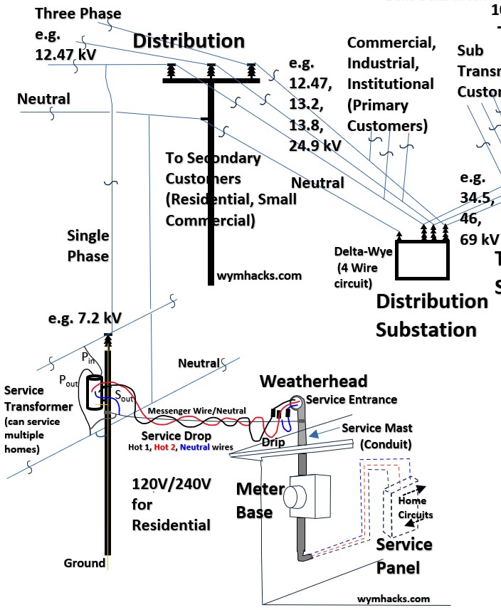
Picture_1: Power Grid: From The Generator to the Home
Picture_2: Power Grid: From The Generator to the Home
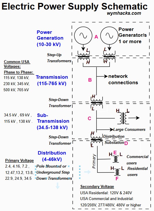
Generation
Whether it’s burning natural gas, nuclear fission, or spinning wind turbines, the plant generates electricity.
Three phase alternating current is produced using the physics of electromagnetic induction (Faraday’s Law).
Usually, this happens at a relatively low voltage (around 11kV to 25kV).
You can read more on Faraday’s law, electric generators, and power plants though my articles:
- Faraday’s Law and Lenz’s Law
- Alternating Current (AC) Generation
- Power Plants (Electricity Producing Facilities)
The Step-Up Transformer
Sending low voltage over long distances is incredibly inefficient because you lose a ton of energy as heat.
- Joule’s Law P = I2R (the heat loss equation) tells us more heat loss occurs as the current increases.
- and the electrical power equation P = VI tells us that voltage and current are the two multipliers that produce power.
- See Appendix 1 in my post Power Plants (Electricity Producing Facilities) to see how efficiency is improved at high voltage and low current.
To fix this, a Step-Up Transformer at the plant increases the voltage up to massive levels—between 100,000V and 765,000V and even higher.
A transformer is a passive electrical device that transfers electrical energy between two or more circuits through electromagnetic induction.
It is primarily used to “step up” (increase) or “step down” (decrease) voltage levels while maintaining the same frequency.
It works on the principle of Faraday’s Law of Induction:
- when an alternating current flows through the primary coil, it creates a varying magnetic field in the transformer’s iron core.
- This fluctuating magnetic flux then passes through the secondary coil, “inducing” a voltage in it without the two coils ever needing to touch.
Picture_3: Power Three Phase Transformer
![]()
You can learn all about transformers in my post: Transformers
Transmission Lines
These are the lines draped on top of giant steel towers you see cutting across the countryside and possibly near your neighborhood.
Picture_4: 2 Circuit Transmission Tower
See much more on above ground electrical structures in my post: Electric Power Line Structures
They carry that high-voltage power over hundreds of miles.
Since the voltage is so high, the wires have to be hung far apart and high up to prevent “arcing” (electricity jumping through the air).
Transmission and Distribution Substations
Power will typically be stepped down a few times (again, via transformers) as it provides power at different levels to different users (sub-transmission users, Primary Customers, and Secondary Customers).
Your home is considered a Secondary Customer so you will be tapping off downstream of what is called a distribution transformer.
Distribution Lines and Connection to Residential (Service) Transformer
Now (you can refer to picture_1 as needed) , the three phase power lines from the distribution substation (and associated step-down transformer) will enter you neighborhood via wooden or metallic poles (or underground sometimes).
We’ll assume that the three phase power lines in your neighborhood are at 12.47 kV and are aboveground on poles.
What you will typically see on these poles is three “hot” wires (usually topmost) and a neutral wire.
This kind of configuration is called a Wye (or Star) 3 Phase, 4 Wire Circuit.
You can read all about wye circuits in my post: Wye and Delta Three Phase Circuits
In the picture below, a Wye circuit is shown where the 3 coils in the circuit (shown with the inductor squiggly line symbol) represent the three secondary coils of the distribution transformer (at the substation somewhere near(ish) your house).
Picture_5: Wye (Star) 4 Wire Circuit
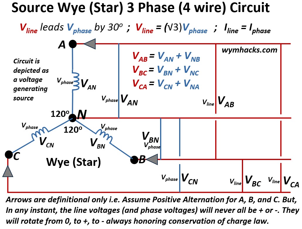
The wires coming off of these 120 degree connected coils are run all the way to a pole near your house.
At this point, the power is still way too high for your house (in our example, its at 12,470 volts).
So, a connection or tap is made off of one of these three phase wires and is routed to your residential transformer.
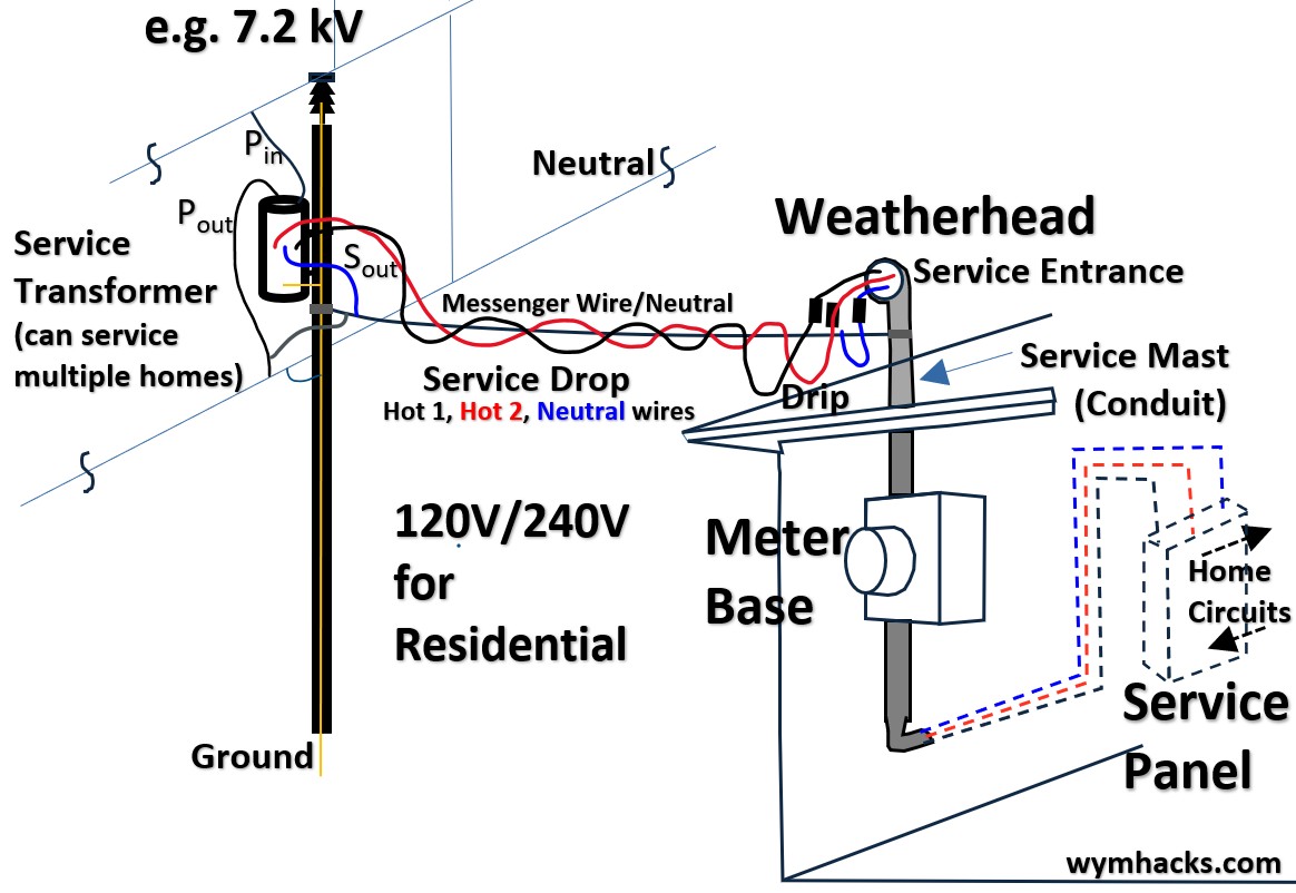
On the other end of the picture above might be the picture below.
Picture_6: 12.47 kV to 120/240V Distribution Transformation
Notice in the picture above that we have a 12.47 kV supply, but “only” 7,200 V are “coming down” the tap to the transformer.
In a three-phase system, the 12.47 kV rating refers to the potential difference between any two of the three hot wires (Phase-to-Phase or Line-to-Line).
However, when you “tap into” a line to power a single-phase transformer, you are connecting one hot wire to a neutral wire.
This transition from line-to-line to line-to-neutral changes the voltage by a factor of √3 (square root of 3 = approximately 1.732) due to the 120° phase displacement in a Wye-configured system.
The picture below shows how the square root of three factor is derived from simple geometry and the isosceles triangle that is drawn from a Wye circuit.
- I also derive it in my post: Wye and Delta Three Phase Circuits
Picture_7: Geometry of the Wye Circuit Means Vline-to-line = Vline-to-neutral√3
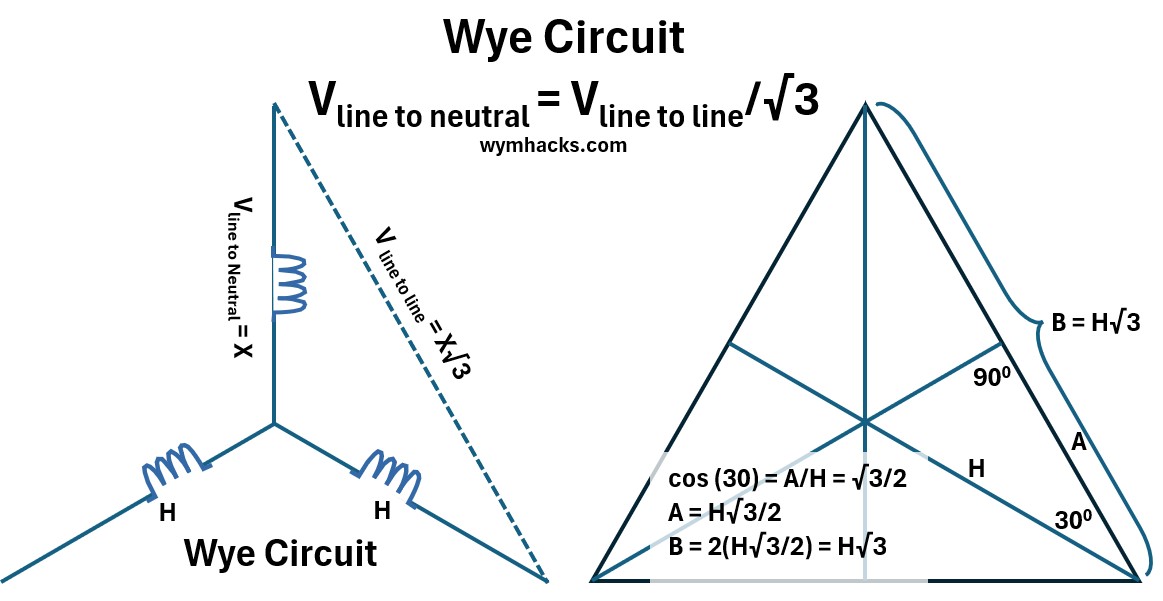
Consequently, dividing the 12,470 V transmission voltage by 1.732 yields the 7,200 V primary voltage required by the residential transformer.
Below is a cleaner picture of the voltage line connectivity’s in a typical pole mounted residential transformer.
Picture_8: Pole Mounted Residential (Service) Transformer Circuits
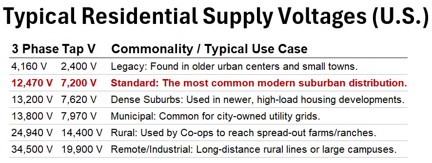
Please note that we have used a 7.2 kV single phase supply example.
Actual supply voltages across the USA might range between 2.4kV and 14.4kV depending various factors (distance being the key one).
Picture_9: Typical Residential Supply Voltage in the USA
Also, in the transformer drawing above, note the connectivities of the Neutral Wire (delivered across the utility poles) to
- the transformer secondary coil outlet Neutral Line and
- the utility pole ground line
Ok, so far we’ve covered the path and all the way to the pole mounted residential transformer
- but remember, that pad mounted transformers (installed on concrete pads on the ground) can deliver power to homes via underground lines.
I’ve zoomed in a little on Picture_1 (see Picture_10 below) so you can see the details a little more clearly.
Picture_10: Grid: Electric distribution System (from Pole to Home)
We want to explore the wiring from the transformer to the house, but before we do, lets take a closer look at the coils inside the pole mounted transformer.
Secondary Coil Side of the Service (Residential) Transformer
The service transformer takes that 7,200V (in our example) and drops it down to the standard 120V/240V used in US homes.
A transformer uses the principle of magnetic induction to change voltage based on the ratio of wire loops (turns = N) around its core.
Vprimary/Vsecondary = Nprimary/Nsecondary
See my post: Transformers for more on the theory and the applicable physics equations.
To drop 7,200 V down to 240 V, engineers design a 30:1 turns ratio.
This means for every 30 wraps of wire on the high-voltage (primary) side, there is only 1 wrap on the low-voltage (secondary) side.
Secondary Coil Side Split-Phase Design
To get the “split” for residential use, the secondary coil is “tapped” exactly in the middle:
Picture_11: Theoretical Internals Of a Residential Transformer (7.2 kV line to neutral supply).
- The Full Coil: Delivers the total 240 V (for heavy appliances).
- The Center Tap: Connected to the neutral wire, it splits that 240 V in half, providing two separate 120 V paths (for standard outlets).
The primary coil is the end of the circuit between it and the secondary coil of the substation transformer.
The secondary coil is the beginning of the circuit between it and the home.
There are 2 Large Circuits Between the Substation Transformer and Your Residential Transformer
The residential transformer coils form the end and the beginning of two large circuits.
Picture_12 below depicts this where
- One hot leg of the substation transformer Wye circuit connects to the residential transformer primary coil
- The outlet of the residential transformer primary coil connects to the neutral
- The secondary coil of the residential transformer primary coil establishes a closed circuit with the home.
Picture_12: The Two Large Circuits Between The Home and The Substation
![]()
The Neutral Wire
Neutral Wire Is not Used In Transmission Sections of the Grid
It might be useful to look at pictures 1 and 10 while you read this section.
Most people assume electricity always needs a dedicated “neutral” return wire to travel, but the high-voltage transmission system is actually more efficient than that.
Above 30 kV, the grid uses a Delta configuration.
In this three-phase setup, the phases act as return paths for one another, eliminating the need for a separate neutral conductor over long distances.
Notice I don’t show a neutral wire in the transmission portions of pictures_1 and 10.
The lone wire you see at the very top of those giant steel towers isn’t a neutral at all—it’s a static “shield wire” designed to catch lightning and carry it safely to the ground (its also called the earth line…see picture_4).
The transition to neutral lines happens at your neighborhood substation.
Neutral Wire Is Used Downstream of the Distribution Transformer
Here, the distribution transformer uses a Delta (Primary Coils)-to-Wye (Secondary Coils) design.
The “Wye” secondary coil creates a central junction point, which is the birth of the System Neutral.
From this point forward, the circuit changes: your street-level power consists of a hot phase and a dedicated neutral return.
This forms a complete “primary” circuit between the substation’s secondary coil and your residential transformer’s primary coil.
At your house, the residential transformer acts as the final bridge.
It takes that street-level power and induces it into a separate, isolated secondary coil, creating a new, closed “split-phase” circuit specifically for your home.
While you will notice your home’s neutral (the messenger wire) is physically tapped into the street’s neutral, this isn’t strictly necessary for the circuit to function.
Instead, it serves as a “safety anchor” or Multi-Grounded Neutral.
By bonding your local loop to the utility’s system neutral, the grid ensures your home’s voltage stays stable at 0V and provides a safe path for surges, keeping your local circuit isolated but grounded.
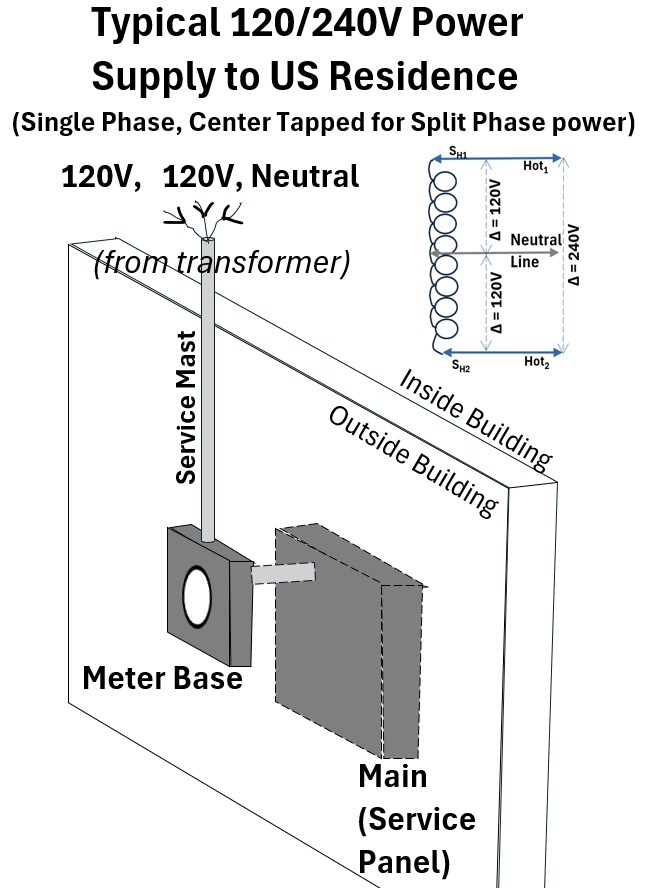
Service Drop to Meter and then to Service Panel
The wires run from the pole transformer to your house (the Service Drop), through your electric meter (where they track how much you’re using), and into your Breaker Panel.
From there, the power distributes into several circuits powering your home.
Each circuit has a breaker which automatically disrupts the circuit at higher than design amps (current).
The Service Drop (Pole to House)
Let’s take a closer look at the pole to house part of the circuit (see picture_13 below).
The collection of wires from the pole transformer secondary coil is called the Triplex.
- It’s called “Triplex” because it comprises three wires twisted together into a single assembly.
- The “Hots” (Phase A and Phase B):
- These are the two insulated aluminum wires.
- Each carries 120V relative to the neutral.
- The “Messenger” (Neutral): This is the bare (uninsulated) aluminum wire in the center.
- The bare wire is the physical “backbone” of the cable.
- It is the only wire under tension; it holds the weight of the entire span so the insulated hot wires don’t stretch and snap.
The Drip Loop and Weatherhead
Picture_13: Service Drop to Home
As the Triplex reaches your house, it is anchored to a “dead-end” porcelain insulator.
Here, it transitions into the Service Entrance Conductors owned by you (the homeowner).
- The Drip Loop: The wires are sagged into a “U” shape before entering the pipe.
- Gravity ensures that rain runs to the bottom of the “U” and drips off, rather than following the wire like a slide directly into your electrical panel.
- The Weatherhead (Service Head): This is the “hooded” cap atop your vertical pipe (the Mast).
- Its job is to keep water out while letting the wires enter.
The Mast and Meter Base
The three wires travel down a vertical pipe (the Service Mast) into the Meter Base.
- Inside the meter base, the wires are separated.
- Neutral: Connects to a center lug, which is also “bonded” (connected) to the metal box and a ground rod.
- Hots: Connect to the top lugs of the meter socket.
- When the utility plugs in the Electric Meter, it bridges the top and bottom lugs to begin measuring your usage.
Into the Panel Box
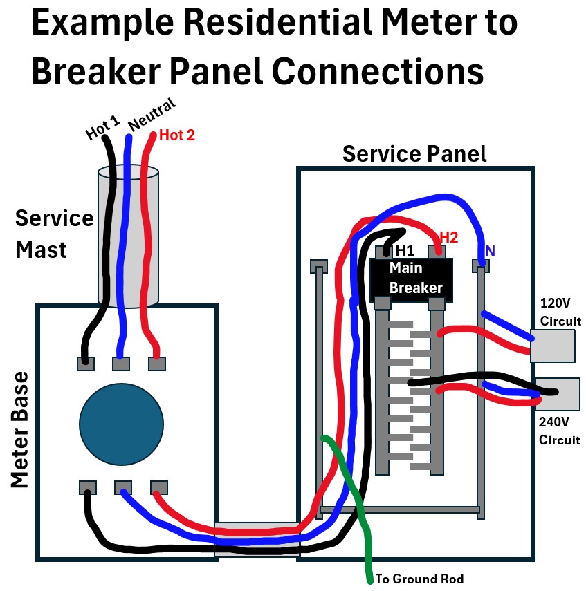
The picture shows the connections to the Service Panel from the meter.
As you follow the general descriptions below, please note that the service panel picture is simplified to show the main “hot” conducting bus bars that the circuit wires connect to.
In reality, when you look at your panel box you’ll see a bunch of switches (breakers) which sit on top of these buses.
We’ll get into more details about the panel box in a later section.
Picture_14: Residential Meter to Breaker Panel (Service Panel) Connections

Three thick wires (the Main Feeders) exit the meter and connect to the Main Breaker (a switch you can turn off to isolate power supply to your home).
Warning: If you turn this switch off , just remember that anything (especially metallic like lug nuts) upstream of the breaker is still energized!!!
The metallic conductor bars (bus bars) with those jutting “fingers” connect to the hot wires and allow voltage to be distributed to the various home circuits.
More on that later.
- Line 1 (Hot)
- Typical Color: Black
- Panel entry description: Main Breaker (Lug 1)
- Purpose Feeds half of your 120V circuits.
- Line 2 (Hot)
- Typical Color: Red (or Black)
- Panel entry description: Main Breaker (Lug 2)
- Purpose: Feeds the other half of your 120V circuits
- Neutral (we’ll color it blue because white on white doesnt show!)
- Typical Color: White (or Taped White)
- Panel entry description: Neutral Bus Bar
- Purpose: The “return path” for all 120V current
In my house, the service drop to the house basically looks like my drawing above.
Yours might look a little different i.e.
- The service lines might come underground
- The service panel might be located inside or outside the home
- There might be an isolation switch (main breaker) between the meter and the panel as well
- etc.
My home’s service panels (I have two actually – main panel and sub-panel) are located inside my garage and the service mast and meter are near them on the outside wall of the garage.
Picture_15: Service Mast to Home Service Panel
Ok, finally, we are technically inside the house at the panel or panels.
Go grab some coffee, and let’s learn more details about the Panel (Panels).
Breaker Panel/s
Ok, so we are now looking at your home’s Service Panel and associated Sub-Panel/s.
Recall that the power coming into the service panel is from the meter (or meter base).
Picture: Meter to Main/Service Panel (Hot Bus Bar Breakers not Shown)
The Service Panel (or load center) is the primary hub for electrical distribution and safety within a home.
It receives the 120/240 V service from the utility transformer and divides it into individual branch circuits for lights, outlets, and appliances.
Its core functions include:
- Distribution: Routing power through a series of “bus bars” to various areas of the house.
- Protection: Housing circuit breakers that automatically disconnect power during an overload or short circuit to prevent electrical fires.
The Role of Subpanels
A subpanel is a smaller, secondary distribution point fed by a high-amperage breaker within the main service panel (not shown above).
They are typically installed to:
- Extend Capacity: Provide more breaker “slots” when the main panel is full.
- Localize Control: Simplify wiring in distant areas like a finished basement, a detached garage, or a large kitchen remodel.
- Organization: Group specific loads—such as all pool equipment or a workshop—under a single, local disconnect point.
While a subpanel distributes power just like the main panel, it remains downstream of the Main Disconnect,
- meaning shutting off the main breaker in the primary panel kills power to all subpanels and the entire house simultaneously
We’ll take a look at a Service Panel + Subpanel layout later on in this post, but let’s come back to the Service Panel.
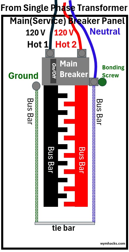
Bus Bars
In a standard U.S. main panel, you have four distinct bars that handle the traffic.
Picture: Service Panel Bus Bars (Hot Bus Bar Breakers not Shown)
note: “bus” originates from the Latin term omnibus, which literally means “for all.”
Hot Bus 1 & Hot Bus 2
- These are the two main “live” vertical pillars in the center.
- Each carries 120 V from the transformer.
- They are staggered so that as you move down the panel, they alternate (A-B-A-B). (the fingers you see)
- Breakers (overcurrent protective switches), not shown above, connect these hot bus bars to the circuits.
- This allows a single breaker to grab 120 V from one, or a double-pole breaker to grab both for 240 V.
Neutral Bus Bar: This is where all the white wires (blue in my drawings) return (as we’ll see in my circuit examples later on)
- It provides the return path for the current to go back to the transformer.
- In a main panel only, this bar is physically “bonded” (connected) to the metal casing of the panel and the ground bar.
Ground Bus Bar: The ground bus bar serves as the collection point for all the green or bare copper Equipment Grounding Conductors (EGC) in your home. Its role is two-fold.
- Fault Current Return (The Life Saver):
- If a “hot” wire touches a metal appliance frame or a junction box, the ground bus bar provides a low-resistance path for that current to travel back to the panel.
- Because of the main bonding jumper (the connection between neutral and ground), that current jumps to the neutral bus,
- heads back to the transformer, and creates a massive overcurrent spike that trips the breaker in milliseconds.
- Without this path back to the source, the appliance frame would simply stay energized and “hot,” waiting to shock whoever touches it.
- Voltage Stabilization (The Earth Connection): The ground bus bar also connects to the Grounding Electrode Conductor (the wire going to your ground rod or water pipe).
- This does nothing to trip breakers.
- Instead, it “pins” your home’s electrical system to the Earth’s potential (0V),
- protecting your house from external surges like lightning or utility line crosses by bleeding that high-voltage energy into the soil.
The “Bonding” Detail: In your main panel, the Neutral and Ground bars are usually tied together by a “bonding screw” or a metal strap.
- This ensures that the entire system has a single, solid reference to “Zero” volts (Ground).
- In the picture above the bonding screw ensures that the neutral bus is connected to the metal case while
- the tie bar electrically connects the neutral bus with the ground bus
- If you ever look at a subpanel, however, these two must be kept strictly separate!
We’ll come back to what a properly wired Main Panel and Subpanel should look like with respect to the grounding equipment.
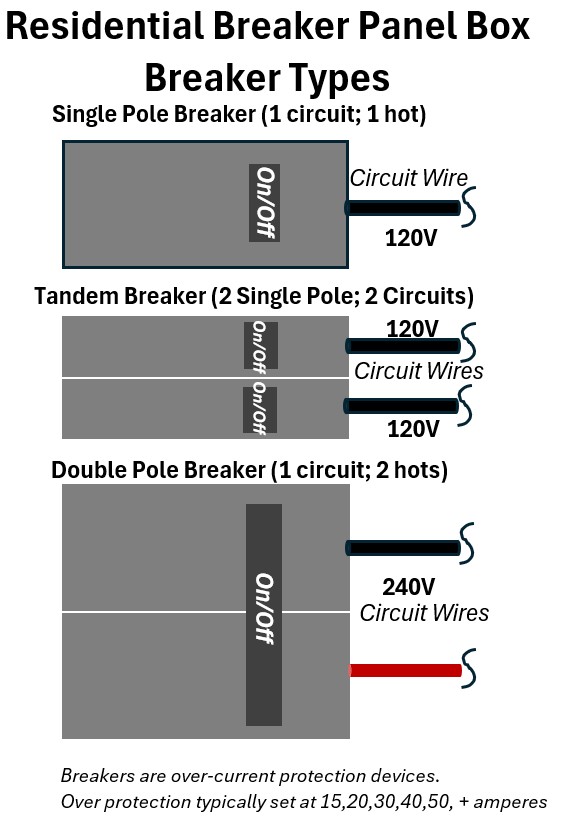
Breakers
Circuit breakers serve as the primary safety interfaces on a panel board, functioning as resettable switches that protect individual branch circuits from overcurrent damage.
Each breaker is designed to monitor the flow of electricity through its internal bimetallic strip or electromagnetic coil;
- if the current exceeds the breaker’s rated amperage—due to an overload or a direct short circuit—the mechanism physically trips,
- severing the connection to the energized bus bar.
- In a standard panel,
- single-pole breakers occupy one slot to provide 120 V,
- while double-pole breakers span two slots to draw from both hot bus bars for 240 V loads.
- Unlike fuses, breakers can be manually reset after the fault is cleared, providing a reliable, long-term solution for localized circuit protection.
Picture: Panel Breaker Types
So, if you opened up your service panel box, you would probably see something more like the picture below (you would of course see a lot more home circuit wires than what I’ve shown).
Notice the subpanel feeders coming out the bottom. These are fed through a double pole 100 A breaker.
- These are routed to a second panel (which I’ll discuss more in the home circuit example 2 section later in this post).
- Subpanels (second panels) are essentially “satellite” hubs for your electrical system.
- You typically see them used for three main reasons: distance, space (i.e. main panel is full), or organization.
Picture: Service Panel Showing Breakers and Example Wiring
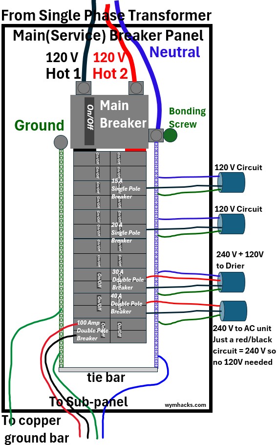
In the example panel above we have variously sized breakers in service
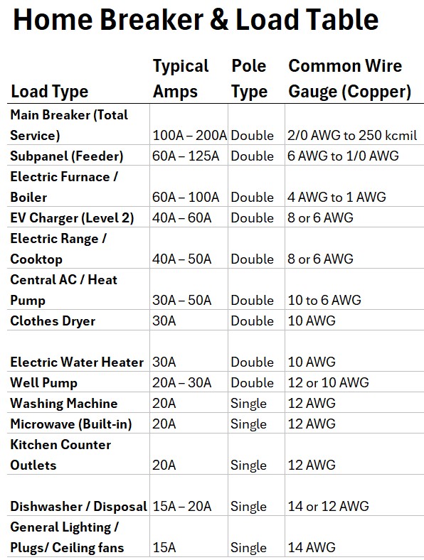
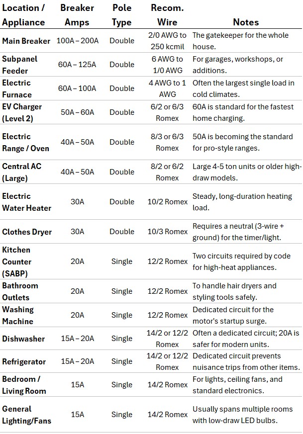
In the table below I’ve listed the typical breaker sizes (Amp ratings) and which appliances are associated with them.
- The largest breakers will be
- the main breaker (200A rating typically)
- and the Subpanel feed breaker (100 A breaker) – Shown on the bottom left in the picture above
- Then you’ll have an assortment of breakers anywhere from 15A to 50A (and more) that protect various power using circuits in your home.
Table: Typical Residential Circuits(1)
Since the last column in the table above lists wire dimensions, lets discuss wires next.
American Wire Gauge
See Appendix 2 for more details
American Wire Gauge (AWG) is the standard system used in North America to denote the diameter of round, solid, nonferrous, electrically conducting wire.
The scale is inverse: as the gauge number increases, the wire diameter actually decreases.
To convert AWG into inches use this formula: d = .005 inches x 92(36-AWG)/39
Romex and Common Designations
When you buy residential wire like Romex (the brand name for NM-B or Non-Metallic sheathed cable), you will see designations that look like “14/2” or “12/3.”
Here is how to read them:
- The First Number: This is the AWG size of the individual conductors.
- The Second Number: This is the number of current-carrying conductors (Hot and Neutral).”With Ground”
- The ground is the bare copper grounding wire and its almost always present but is not counted in the numbering
- e.g., “14/2” actually contains three wires total.
- 14/2 ; Lighting circuits, general outlets; 15 Amps
- 12/2; Kitchen outlets, bathroom circuits, power tools; 20 Amps
- 10/3; Electric clothes dryers, water heaters ; 30 Amps
- 8/3 or 6/3; Electric ranges, large subpanels; 40–55 Amps
Table: Typical Residential Circuits(2) with Recommended Wire
Ok, it’s time to walk through a simple home circuit example.
Example Home Bedroom Circuit
Consider the example circuit wiring schematic below for a home bedroom where I show
Picture: Example 15 Amp Home Bedroom Circuit (With AFCI)
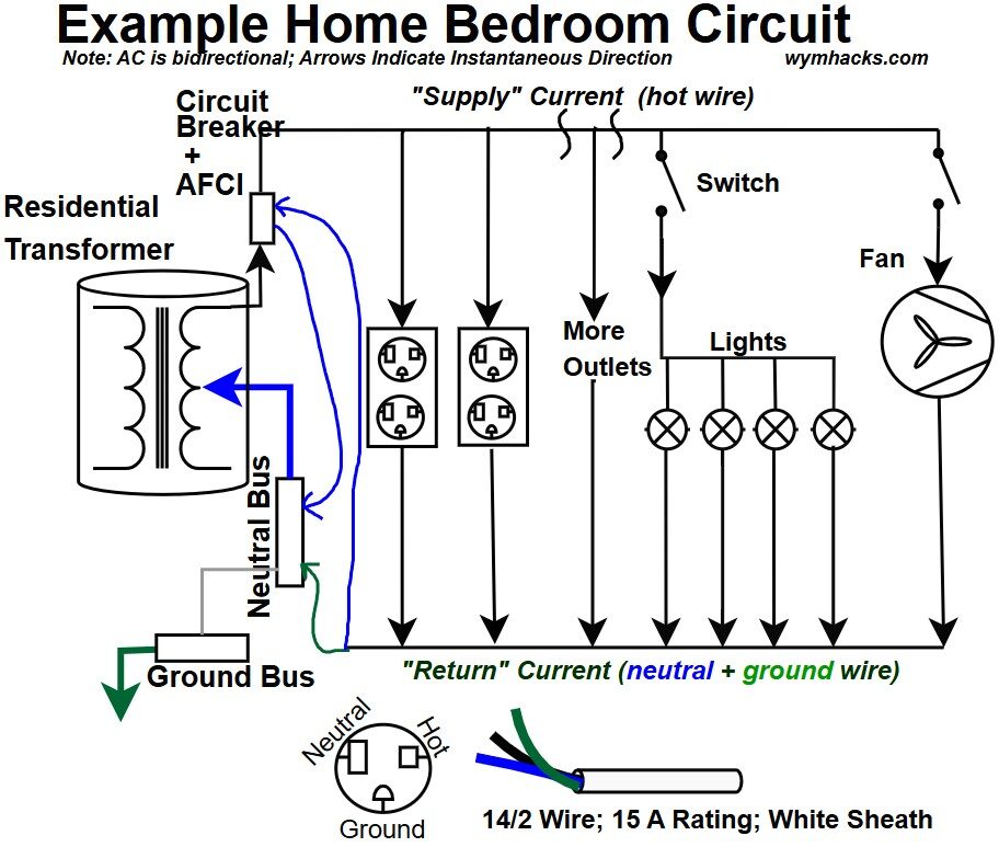
- the full home circuit for a branched circuit which shows the secondary coil of the residential transformer (which is the start and end point for each home circuit).
- the AC flow in a given instantaneous direction (but, we remember that at every moment the AC “flickers” back and forth bidirectionally).
- a hot 120V wire coming off of the transformer routed through the home breaker box through a
- 15 A Circuit breaker with ACFI functionality.
- The run of wire from the breaker to the first element is sometimes called the Homerun.
- The AC goes in parallel through several outlets, ceiling lights, and a fan.
- The electric wiring to and from each of the elements is “14/2” wire meaning (for a Romex (NM-B cable))
- it’s rated for 15 amps and has three wires:
- a 14 AWG Black (Insulated) hot wire
- a 14 AWG White (Insulated) neutral wire (colored blue in my drawing)
- a 14 AWG Bare Copper (Ground)
- The hot 120V black wire of the 14/2 connects to the circuit breaker as does the neutral wire (white but we color it blue for visibility against the white background)
- A neutral wire from the AFCI breaker (pigtail) then connects to the neutral bus bar (so the circuit completes by going back to the transformer middle coil)
- The ground wire connects to the neutral bus (in the primary service panel) which is connected to the ground bus (otherwise we would route this to the ground bus).
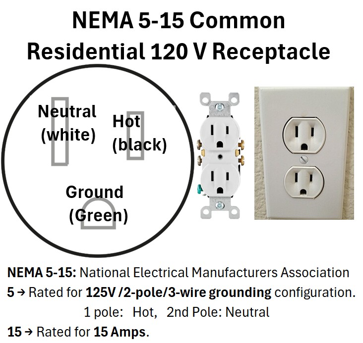
- I show a standard NEMA 5-15R receptacle (wall outlet). There will be some other plug/receptacle types in your home (see Appendix 3 for more information).
Design Review of The Bedroom Circuit
The Load Calculation
To see if 15 amps is enough, we calculate the Wattage.
A 15-amp circuit at 120V provides a total of 1,800 Watts (P = IV = (15 A)(120V) = 1800 W = 1.8 kW
- 4 Ceiling Lights (LED); 10W each; (10 x 4W)/120V = 0.33A
- Ceiling Fan (High Speed); 80W ; 80/120 = 0.66A
- 6 Outlets (General Use)~1,200W/120V = 10.0A
- TOTAL ESTIMATED LOAD; 1,320 Watts; 11.0 Amps
The Verdict: 11.0 Amps is well under your 15-amp limit.
- Even under the “80% Continuous Load Rule” (which limits you to 80% x 15 = 12 Amps for long periods), you are still in the safe zone.
You’ve got some options here to make the circuits a little more robust because adding high amp appliances like space heaters or vacuum cleaners could trip your circuit.
Consider adding in two circuits to wire the bedroom which gives you ample amp (ha ha) room to use those wall outlets.
- A 20 A AFCI system for the outlets (using 12/2 wire)
- A 15 A AFCI system for the lights and fan
Parallel vs Series
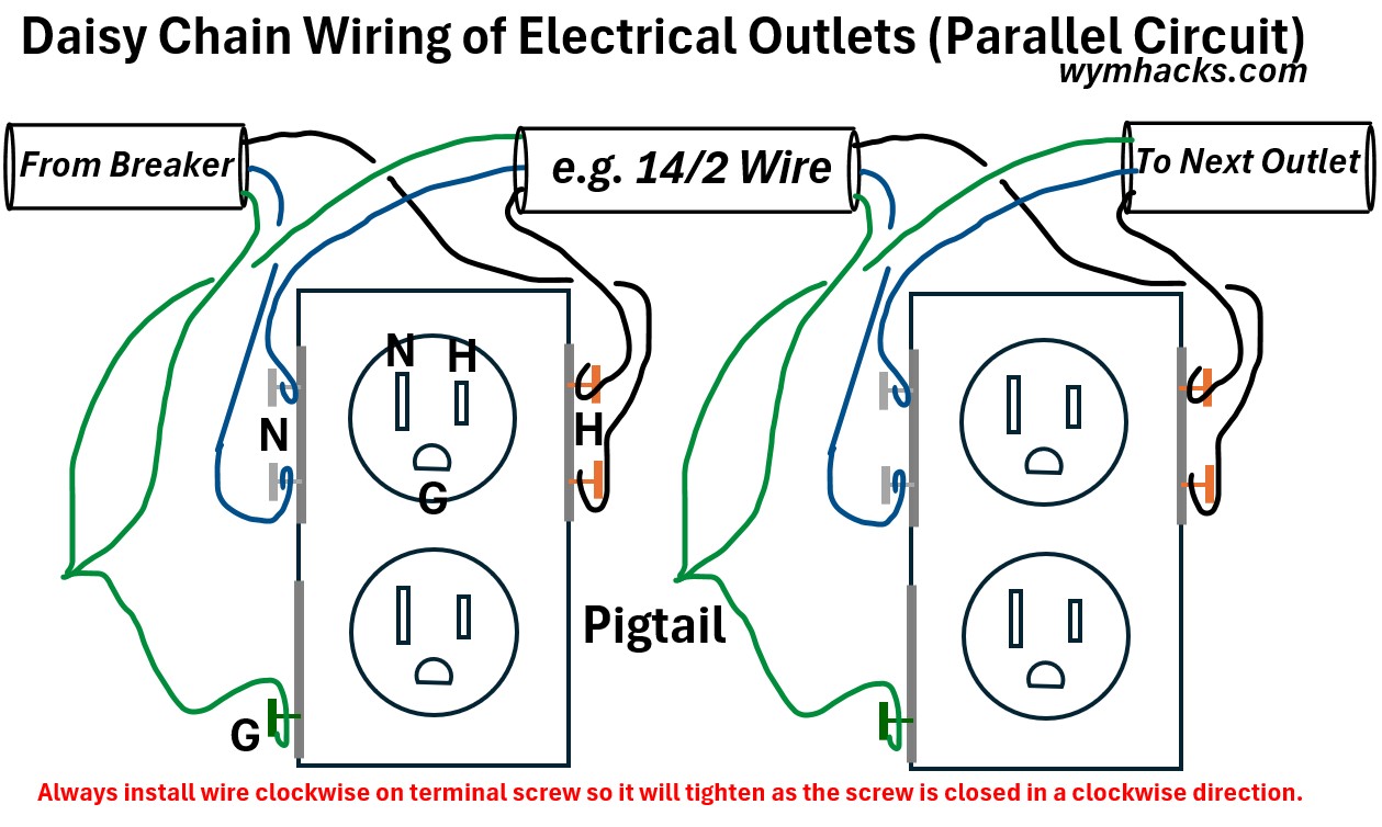
I was trying to view some videos on line and found some DIY videos describing the technique of daisy chaining (see picture below) wiring outlets (or lights etc.) together.
The presenter used the words daisy chaining the outlets in series.
- Technically, the process of connecting these outlets does involve connecting one to the next so, yes, in that context they are in series.
- But the electrical supply is flowing in parallel (and what we normally do in home circuits).
- We want the elements in parallel because
- We use Parallel because it ensures every device gets the same “pressure” (Voltage) and operates independently.
- Consistent Voltage: Every outlet and light in your bedroom gets the full 120V.
- In series, that voltage would be split (e.g., 20V to the fan, 50V to a lamp), causing them to fail or run weak.
- Independence: If you turn off a light or a bulb burns out, the rest of the circuit stays live. In series, one “off” device breaks the loop for everyone.
- Variable Current: Devices can pull exactly the “flow” (Amperage) they need.
- A phone charger can pull 0.1A while a vacuum pulls 12A on the same parallel line without interfering with each other.
- The Layout: You connect all Black wires together and all White wires together at every box. This creates a “ladder” where each load is its own independent rung.
- Be aware though that if we have An AFCI outlet or GFCI outlet it will be installed upstream of certain elements which would be impacted by its activation.
Picture: Daisy Chain Wiring of Electrical Outlets
Let’s now look at an example where we have a circuit coming off of a sub breaker panel.
Typically you’ll have a sub-panel if you’ve run out of space for breakers in your main panel (service panel).
This configuration brings up some nice safety issues which should be aware of so let’s review another example.
Home Circuit Example with Main Panel and Sub-Panel.
Check out the circuit below where I show a full circuit for a 240V residential electrical dryer.
In this example, I’m assuming the home has a sub-panel to accommodate all the breakers this home needs.
In my home these panels are located inside my garage near the service mast that brings the wires in from the outside transformer.
You wont be able to see the exact wiring organization and routing without removing the front metallic section that the breakers are embedded in:
This plate has different names:
- Dead Front Cover: The technical industry term.
- Inner Cover: To distinguish it from the outer “trim” or the door itself.
- Trim Plate: Often used when referring to the entire front assembly (the door and the flat plate together).
Picture_1 – US Residential Circuit Example; 30 A Circuit; 2 Panel Home; Drier Circuit
![]()
This time we have a dedicated circuit to power our fancy electric drier.
- Two 120 volts hot lines (1 and 2) come from the ends of the secondary coil in the residential transformer
- In the main service panel a 100 A double pole breaker routes the two hot wires to the subpanel
- In the subpanel, a double pole 30A breaker (with GFCI built in as well) connects to the two hot wires of a 10/3 cable (often by Romex).
- 10/3 cable wire has 10 AWG thickness and has 2 hot wires, 1 neutral, and 1 ground.
- The second number indicates the number of wires that normally carry current
- If you are buying modern NM-B cable (commonly called Romex), the outer jacket of a 10/3 cable is Orange.
- Let’s follow the wires into the drier ( the picture_2 below)
Picture_2 – US Residential Circuit Example; 30 A Circuit; 2 Panel Home; Drier Circuit
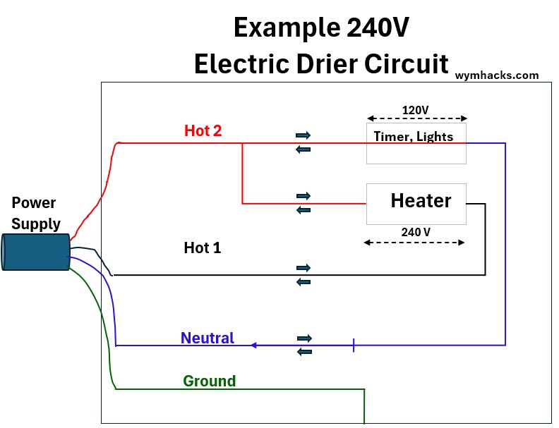
- the hot 2 wire connects to the timer, light, and heater
- the return circuit from the timer/nights is the neutral wire (voltage across is 120V)
- the return circuit from the heater is the other hot wire, hot 1 (voltage across is 240V)
- the ground is attached the steel body
Neutral Wire Path
Ok, jump back to picture_1 for the return path to the transformer to complete the circuit
The neutral wire connects to the GFCI breaker and then via a pigtail connects to the neutral bus (n1 to n2 in picture_1).
- A GFCI breaker compares the electricity leaving on the Hot wire with the electricity returning on the Neutral wire.
- In a perfectly safe circuit, these two numbers should be identical.
- Scenario A (Safe): 5 Amps go out on the Hot, 5 Amps come back on the Neutral. The GFCI is happy.
- Scenario B (Fault): 5 Amps go out on the Hot, but only 4.995 Amps come back on the Neutral.
- Where did that missing 0.005 Amps go?
- The GFCI assumes it is leaking out somewhere it shouldn’t be—possibly through a person, a puddle of water, or a frayed wire.
- Because the Neutral is routed through the breaker, the internal sensor can “see” that missing current and trip the power in milliseconds.
- Under normal conditions the current returns to the transformer via n3-n4-n5-n6 (in picture_1)
Grounding System
Warning: Disclaimer: The information provided here is for educational and informational purposes only and represents my personal understanding of residential electrical systems. It does not constitute professional engineering or electrical advice, nor does it establish a professional-client relationship. Electrical work is inherently dangerous and governed by specific local, state, and national codes (such as the NEC). Before performing any electrical work, you must consult with a licensed, qualified electrician in your specific city and country to ensure compliance with local regulations and safety standards. You assume all risk for any actions taken based on this information.
- The ground wire attaches to the Subpanel Ground Bus Bar g1 to g2. (in picture_1)
- My understanding is that the Subpanel Ground Bus Bar and Neutral Bus Bar should not be connected.
- My understanding is that a Main Bonding Screw (Jumper) should not be used in the Subpanel.
- The Main Bonding Screw (aka Main Bonding Jumper) connects the Neutral Bus to the metal case.
- then it connects to the Main Panel Grounding Bus Bar at g3 (in picture_1)
- the g2 to g3 wire is called the Equipment Grounding Conductor
- Normally no current is flowing in the ground wire
The Purpose of The Grounding System
Warning: Disclaimer: The information provided here is for educational and informational purposes only and represents my personal understanding of residential electrical systems. It does not constitute professional engineering or electrical advice, nor does it establish a professional-client relationship. Electrical work is inherently dangerous and governed by specific local, state, and national codes (such as the NEC). Before performing any electrical work, you must consult with a licensed, qualified electrician in your specific city and country to ensure compliance with local regulations and safety standards. You assume all risk for any actions taken based on this information
The purpose of a properly installed ground wiring is safety.
It provides a dedicated, low-resistance path for “stray” electricity to return to the source (the panel containing the main service breaker) to instantly trip the circuit breaker.
Lets say one of the hot wires shakes loose and touches the metal of the drier (called a Ground Fault).
- Now the drier is energized ready to shock you when you touch it.
- In this scenario, the current rushes through the metal to the ground wire
- My understanding is that the path it should take in a properly installed main panel and subpanel is:
- g1→g2→g3→g4→across the connection to the neutral bus bar (bonded to it we say)→n5→n6 and back to the transformer
- This happens with a rush of current because there is very little resistance in the circuit any more
- And this will almost immediately trip the 30A breaker in the Subpanel.
According to my readings of the NEC code, in order for this to work properly we have to make sure that
- The Neutral Bus is only connected to the case (and/or Ground Bus Bar) in the panel that has the main breaker
- This connection is called Main Bonding Jumper.
- If you have a dedicated Main Disconnect Panel, then the Neutral and Ground Bus Bars would be bonded in this panel.
- This requirement is stated in Section 250.24(B) of the NEC (National Electric Code…updated in 2026).
- Please see this video for on this : Subpanels Explained – Engineering Mindset
- In our circuit example in picture_1, the bond from the Grounding Bus to the Neutral Bus (Main Bonding Jumper) is in the Main Service Panel
- I show both the metal bridge bond as well as the green screw connection to the case (the Main Bonding Jumper).
- I assume that they serve the same purpose and having them both is probably better.
- The Neutral Bus is only connected to the case (and/or Ground Bus Bar) in the panel that has the main breaker
Design for No Objectionable Current
The reason we want to install our grounding system properly is that we don’t want current normally flowing in parts of the systems that should have no current.
The NEC calls this Objectionable Current and Section 250.6 of the NEC is dedicated entirely to this topic.
The Code in a Sentence states that:
- grounding and bonding must be installed in a manner that prevents current from flowing over the grounding conductors or metal equipment parts,
- except in the case of a temporary ground fault (where a properly installed Main Bonding Jumper is located only in the panel with the main service disconnect)
- NEC Prohibition (250.6(A)) states that Grounding systems must be designed and installed to prevent an “objectionable flow of current” over grounding conductors or paths.
In a properly configured electrical system, the grounding system is a “dead-end” safety network.
Per NEC 250.24(B), the Main Bonding Jumper is required to connect the neutral bus (grounded conductor) to the equipment grounding conductor at the service disconnect only.
- This single-point bond establishes the 0V reference for the building.
- Because the neutral and ground are kept separate everywhere else, the grounding wires and metal conduits have no return path to the transformer.
- They sit at zero potential with zero current, serving as a dormant emergency lane.
The danger of improperly bonding the neutral and ground in a subpanel—defined by the code as being on the “load side” of the service—is explicitly prohibited by NEC 250.24(A)(5).
The primary hazard here is not that the circuit breaker will fail to trip during a short circuit; rather, it is what happens during normal operating conditions.
- By creating that second bond, you violate NEC 250.6, which forbids the installation of grounding conductors in a way that creates “objectionable current.”
- You have effectively turned the entire grounding system into a parallel return path for neutral current.
- Because electricity follows all available paths in inverse proportion to their impedance,
- a significant portion of the return current will now travel through the green wires, metal conduits, and equipment enclosures to get back to the main panel.
- Under the physics of voltage drop (V = I R), this current creates a potential difference on every metal surface in that path.
- Consequently, the metal casing of your appliances and the subpanel itself are no longer at 0V; they are “energized” relative to the earth.
- This creates a persistent shock hazard and “stray voltage” that can lead to fire or injury, as the very system meant to protect you is now a live part of the circuit
Consider reviewing these two great videos on this topic
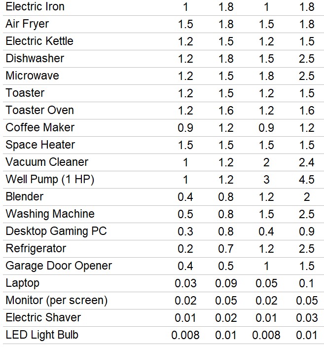
Appendix 1 – Home Appliances Average and Startup Power Usages
Table: Home Power Users (Average and Starting Usage)
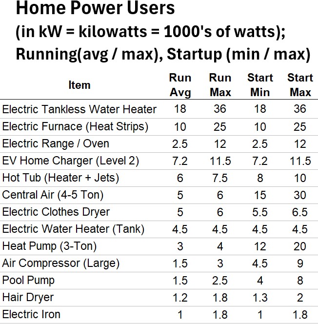
Table: Home Power Users (Average and Starting Usage) – Continued
Appendix 2 – US Residential Electrical Wire Specifications
Table: US Residential Wire Specs NEC 2023 Standards
(Example: Use a 14/2 (14 AWG + 2 conductor + ground) Wire for a 15A circuit that has lights, receptacles , and ceiling fans in the bedroom)
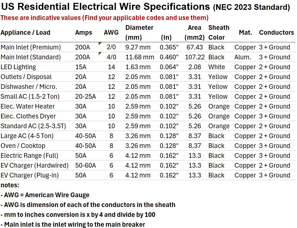
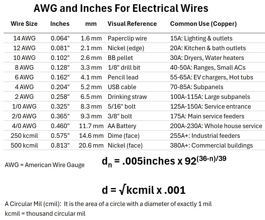
Table: AWG and Inch Equivalences for Electrical Wire
Appendix 3 – Typical Power Outlets (Receptacles) In a US Residence
The Standard “Everywhere” Outlets (120V)
These handle your day-to-day electronics.
- NEMA 5-15R: The standard 3-prong outlet found in every room. 15 Amps.
- Standard residential receptacles are typically 125 V / 15 A NEMA 5-15R duplex outlets, designed to accept three-prong grounded plugs.
- NEMA 5-20R: The “T-slot” outlet. Found in kitchens and garages. 20 Amps.
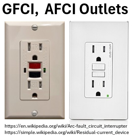
- GFCI: The one with the “Test/Reset” buttons. Required near water (sink, bath, outside).
- AFCI: Looks like a GFCI but protects against fire-starting sparks. Required in living areas.
Picture: NEMA 5-15 Common 120V Receptacle
Picture: GFCI , AFCI Outlets
There are a bunch of other types of receptacles as well.
Table: Common Outlet Types in US Residences
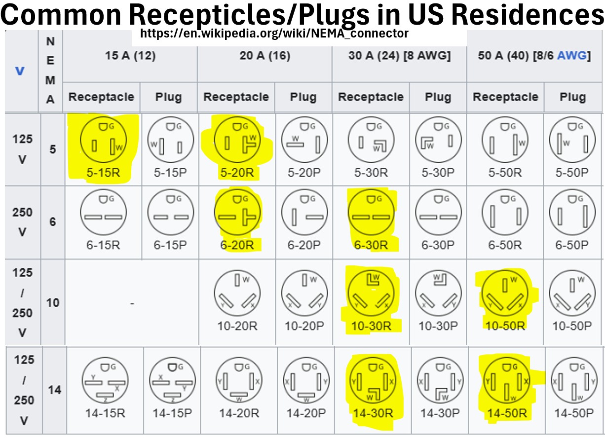
The Mid-Range Heavy Hitters (240V)
Usually for window ACs, large shop tools, or specialized equipment.
- NEMA 6-20R: Two horizontal slots and a round ground. Used for large window/wall AC units.
- NEMA 6-30R: Similar to the 6-20R but beefier. Used for heavy workshop machinery or commercial-grade window ACs.
The Big Appliances (The “Dryer” Group – 30A / 240V)
- NEMA 10-30R: The Old 3-Prong. (Two angled slots, one “L” slot). Common in pre-1996 homes. No dedicated ground.
- NEMA 14-30R: The Modern 4-Prong. (Two hots, one neutral, one round ground). Standard for all new dryer installs.
The Massive Appliances (The “Range” Group – 50A / 240V)
- NEMA 10-50R: The Old 3-Prong Stove. (Two angled slots, one flat vertical slot). Legacy range outlet.
- NEMA 14-50R: The Modern 4-Prong Stove. The big boy. Used for ranges and is also the industry standard for EV Level 2 Charging.
The Hardwired Beast
Central AC Condenser: No plug. It uses a Weatherproof Disconnect Box (Pullout or Switch) and a flexible “whip” (conduit) wired directly into the unit.