Above Ground Structures in the Power Grid
Picture: Electric Grid
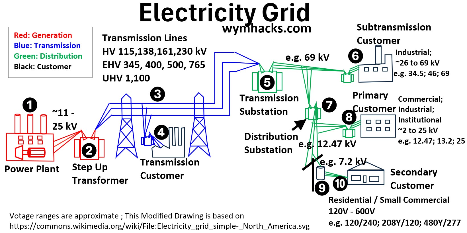
The modern electrical grid is a sprawling network designed for the instantaneous delivery of energy, and its most visible components are the above-ground structures that serve as its backbone.
From massive steel transmission towers to the wooden poles on residential streets, these structures are critical infrastructure;
- they provide the necessary height and physical separation to transport high-voltage electricity safely over long distances and through local communities.
Without this overhead framework, the cost and complexity of maintaining the global energy supply would increase exponentially.
However, the grid is not always visible.
While overhead lines are the standard in many regions due to their lower installation cost and ease of repair, underground supply is increasingly common in other parts of the world.
In high-density European cities—such as those in Germany and the Netherlands—nearly the entire distribution network is buried to protect it from severe weather and to preserve the aesthetic integrity of the landscape.
While this article focuses on the specialized hardware of above-ground systems, it is important to recognize that the global grid is a hybrid of these two worlds, each chosen based on the specific geography, density, and reliability needs of the population.
Transmission & Sub-transmission Structures
These are the heavy-duty structures.
Transmission towers are the massive steel lattices, while sub-transmission structures are often smaller steel or concrete poles.
Picture: Electric Power Line Structures by Type
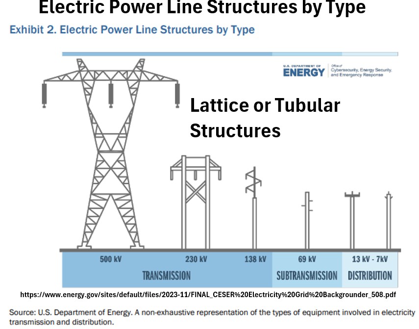
The height and capacity of electrical structures are directly proportional:
- as the voltage increases, the structure must grow taller to maintain safe “air clearance” from the ground and objects below.
- Transmission towers typically stand between 100 and 200 feet tall to carry massive capacities of 230 kV to 765 kV, ensuring that the high-energy arcs cannot reach the earth.
- distribution poles are much shorter, usually ranging from 30 to 60 feet, as they carry lower capacities (typically under 35 kV) that require less physical separation for safety.
- Subtransmission structures act as the middle ground, often standing 50 to 100 feet tall.
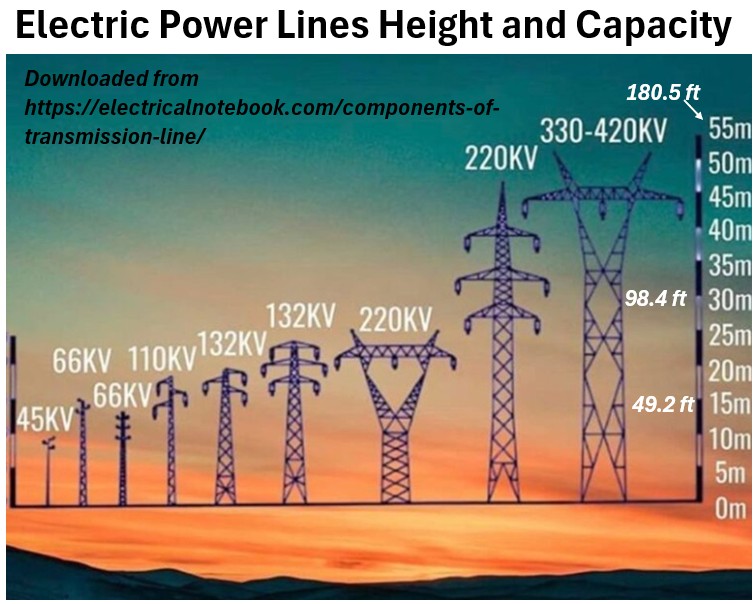
Ultimately, the height is a calculated safety buffer: the higher the capacity, the larger the “strike distance” electricity can travel through the air, necessitating a taller and more robust structure.
Picture: Electric Power Structures – Height and Capacity
Structural Components
Line Supports (The Tower/Pole)
The main structure that provides the height needed to keep high-voltage lines a safe distance from the ground.
Cross-arms
The horizontal beams extending from the tower.
These hold the conductors far enough away from the grounded tower body to prevent electricity from “arcing” through the air.
Conductors
The actual wires carrying the power.
On transmission lines, these are usually ACSR (Aluminum Conductor Steel Reinforced)—aluminum for conductivity and steel for the strength to hang over long spans.
Picture: Transmission Wire Types
When we talk about the actual configuration of wires on a tower, we move from the materials to the geometry of the grid.
This is where engineers balance electrical capacity with the physical limitations of the tower.
Circuits and Phases
A “circuit” refers to a complete set of wires required to transmit three-phase alternating current (AC).
- Single-Circuit Tower
- Carries three phases (three distinct wire sets). If one line fails or needs maintenance, the entire path is often de-energized.
Picture: Transmission Tower (1 Circuit)
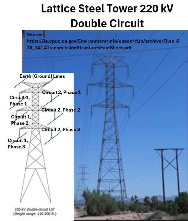
Picture: Transmission Tower Single and Double Circuit
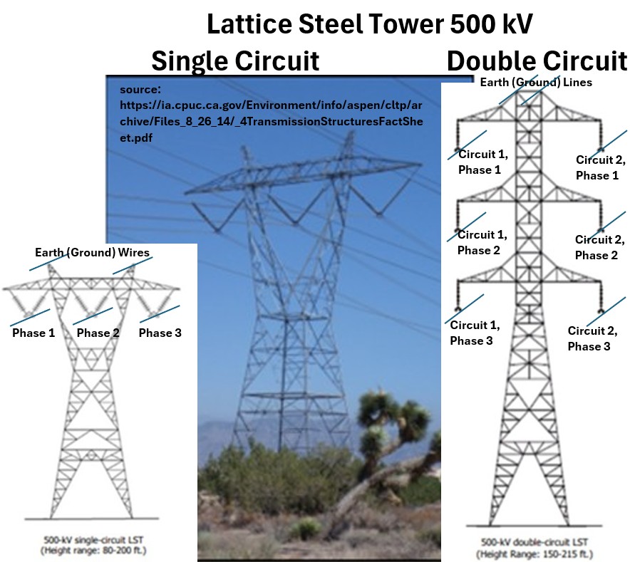
- Double-Circuit Tower
- Carries two independent sets of three phases (six wire sets total). This is the most common high-voltage configuration because it provides redundancy—if one circuit trips, the other can usually handle the load.
Picture: Transmission Tower (2 Circuits)
Picture: Transmission Tower (2 Circuits)
- Multi-Circuit Tower
- In crowded areas with limited “Right of Way,” you may see towers carrying four or even more circuits stacked vertically.
Bundled Conductors
As voltage increases (typically above 220 kV), a single wire is no longer efficient due to Corona Discharge (energy “leaking” into the air, often heard as a buzzing sound).
To fix this, engineers “bundle” multiple wires together to act as a single phase.
- Twin Bundle (2 wires): Standard for 220 kV – 400 kV lines.
Picture: Transmission Tower (2 Circuits; Twin Bundles)
Picture: Transmission Tower (2 Circuits, Twin Bundles)
- Triple Bundle (3 wires): Common for 400 kV – 500 kV.
Picture: Transmission Tower (1 Circuit, Tri Bundled)
- Quad Bundle (4 wires): Used for 500 kV and 765 kV “Super Grids.”
Picture: Transmission Tower (2 Circuits; Quad Bundled)
- Hexa Bundle (6 wires): Seen on Ultra-High Voltage (UHV) lines, like those in China or Brazil.
Spacers and Spacer Dampers
When you have a bundle of wires, they want to behave badly.
High currents create magnetic fields that pull the wires toward each other, while wind tries to slap them together.
- Spacers
- Small metal frames placed every 50–70 meters along the span.
- They maintain the exact geometric distance between the wires in a bundle to ensure the electrical field remains uniform.
Picture: Transmission Line 4 Wire Spacer
- Spacer Dampers
- A more advanced version that includes flexible “joints.”
- These serve a dual purpose:
- they maintain the spacing and act as vibration absorbers (similar to the Stockbridge dampers we discussed earlier) to prevent the bundle from swaying or galloping during storms.
Line Insulators
Usually long strings of porcelain or glass discs.
They are the “buffer” between the energized conductor and the metal cross-arm. The higher the voltage, the more discs you’ll see in the string.
Picture: Transmission Tower Insulator
![]()
Protection & Hardware
Earth Wire (Shield Wire)
The very top wire.
It’s “dead,” meaning it carries no power; its only job is to take a lightning hit so the conductors don’t have to.
Picture: Transmission Tower Earth Line
![]()
Vibration Dampers
Those little “weights” on the lines.
They stop the wind from vibrating the wires to the point of snapping (fatigue).
Picture: Transmission Line Damper
Jumpers
Short, slack wires that “jump” the electricity from one side of a tower to the other at corners, where the main lines are bolted down and can’t turn the corner themselves.
Picture: Transmission Tower (1 Circuits, Tri Bundled) Showing Jumpers
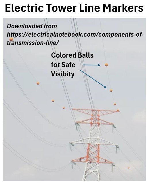
Marker Balls
Those brightly colored spheres you see hanging on power lines—usually orange, red, or yellow—are known as Aerial Marker Balls (or visibility markers).
Their primary purpose is to make the thin, hard-to-see transmission wires visible to pilots of low-flying aircraft.
Picture: Electric Power Line Markers for Visibility
Typical North American Distribution Pole
Key Components
We’ll describe the main components of those power lines you’ll see in your neighborhood (in the US)
Line Supports
Typically 30–60 foot wooden poles.
Picture: Typical North American Utility Pole
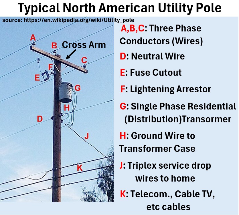
Fuse Cutout (E in the drawing)
A critical safety switch.
If a tree branch hits the line, for example, the fuse inside “blows,” and the tube drops down (literally hanging by a hinge) to disconnect the power and show linemen exactly where the problem is.
A fuse cutout is an overcurrent protector that uses a sacrificial link to shield the distribution transformer from damage.
The Overcurrent Trigger: When an electrical fault (like a short circuit) causes current to exceed safe levels, the fuse link inside the tube melts instantly from the heat.
Mechanical Disconnection: The melting of the link releases a spring-loaded latch that was holding the tube in a closed, “energized” position.
Visual Indication: Without the link’s tension, gravity pulls the tube into a “drop-out” position, where it hangs open. This creates a physical air gap that stops the flow of electricity and serves as a visible signal to utility crews that the overcurrent protection has been triggered.
I love this video on fuse cutouts…watch it!: Transformer Fuse That Powers My Oil Wells.
Lightning (Surge) Arrestor (F in the drawing)
A small, ribbed cylinder (see the picture of it below installed on the inlet wiring to a residential pole transformer).
If lightning strikes nearby, this acts like a pressure relief valve, dumping the massive surge of voltage into the ground before it can fry your TV or the transformer.
A surge arrestor (or lightning arrestor) is a voltage-limiting device installed at the transformer inlet to protect the equipment from high-voltage spikes, such as those caused by lightning or switching surges.
The Component: It consists of a stack of Metal Oxide Varistors (MOV)—a material that acts like a smart valve.
Normal Operation: Under standard voltage, the arrestor has extremely high resistance, acting as an insulator so no electricity flows through it.
The Surge: When a high-voltage spike hits the line, the MOV material instantly “flips” and becomes a high-speed conductor.
The Diversion: It provides a low-resistance path, dumping the excess energy safely into the ground wire before the surge can reach and destroy the transformer’s internal windings.
Reset: Once the voltage returns to normal levels, the arrestor automatically returns to its high-resistance (insulating) state.
Key Distinction: Unlike a fuse cutout, which protects against overcurrent (too much flow), the surge arrestor protects against overvoltage (too much pressure).
Distribution Transformer (G in the drawing above and also see picture below)
The gray “can” that converts high-voltage distribution power into the 120V/240V your house uses.
Picture: Distribution Transformer
A residential single-phase pole-mounted transformer is a step-down device that converts high-voltage distribution power (e.g., 7,200V or 13,200V) into the lower 120V/240V used in homes.
- Exterior: Housed in a cylindrical, oil-filled steel tank (the “bucket”) that acts as both an insulator and a coolant for the internal coils.
- High-Voltage Bushing: A large porcelain insulator on top where the “hot” primary wire enters.
- Low-Voltage Bushings: Typically three smaller terminals on the side that connect to the service drop wires.
- Internal Operation: It uses electromagnetic induction between a primary and secondary coil to “step down” the voltage while maintaining the same frequency.
- Center Tap: The secondary coil is “tapped” in the middle (the neutral), allowing for two 120V circuits that combine to provide 240V for heavy appliances.
See my post on transformers for much more: Transformers
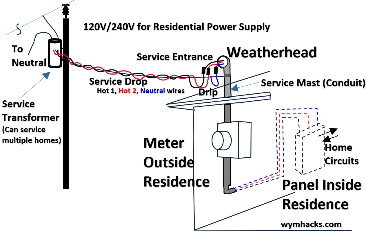
Service Drop
See the picture below and its component J in the “Typical North American Utility Pole” picture above.
The Service Drop is the wires running from the transformer to your house (the “service drop”).
It’s the final bundle of electrical cables that carries power from the utility’s distribution pole to a customer’s building.
Construction: It typically consists of two insulated “hot” wires wrapped around a bare, high-strength neutral messenger wire (known as triplex cable).
The Connection: It connects to the grid at the transformer and terminates at the building’s weatherhead (or service mast).
Purpose: It provides the final 120V/240V service required to power residential appliances.
Clearance: It is designed with a specific “drip loop” at the building side to prevent rainwater from running down the cables and into the electrical meter.
Picture: Service Drop
Neutral Wire
This wire is seen as D in the “Typical North American Utility Pole” picture above. (you can see it in the transformer picture above also)
It is the return path for the circuit, usually found just below the transformer.
Telecom Wires
These are seen as K in the “Typical North American Utility Pole” picture above.
These are the phone, tv, internet lines which are typically located at the lowest levels of the pole.