Where are the Power Generators in the Grid?
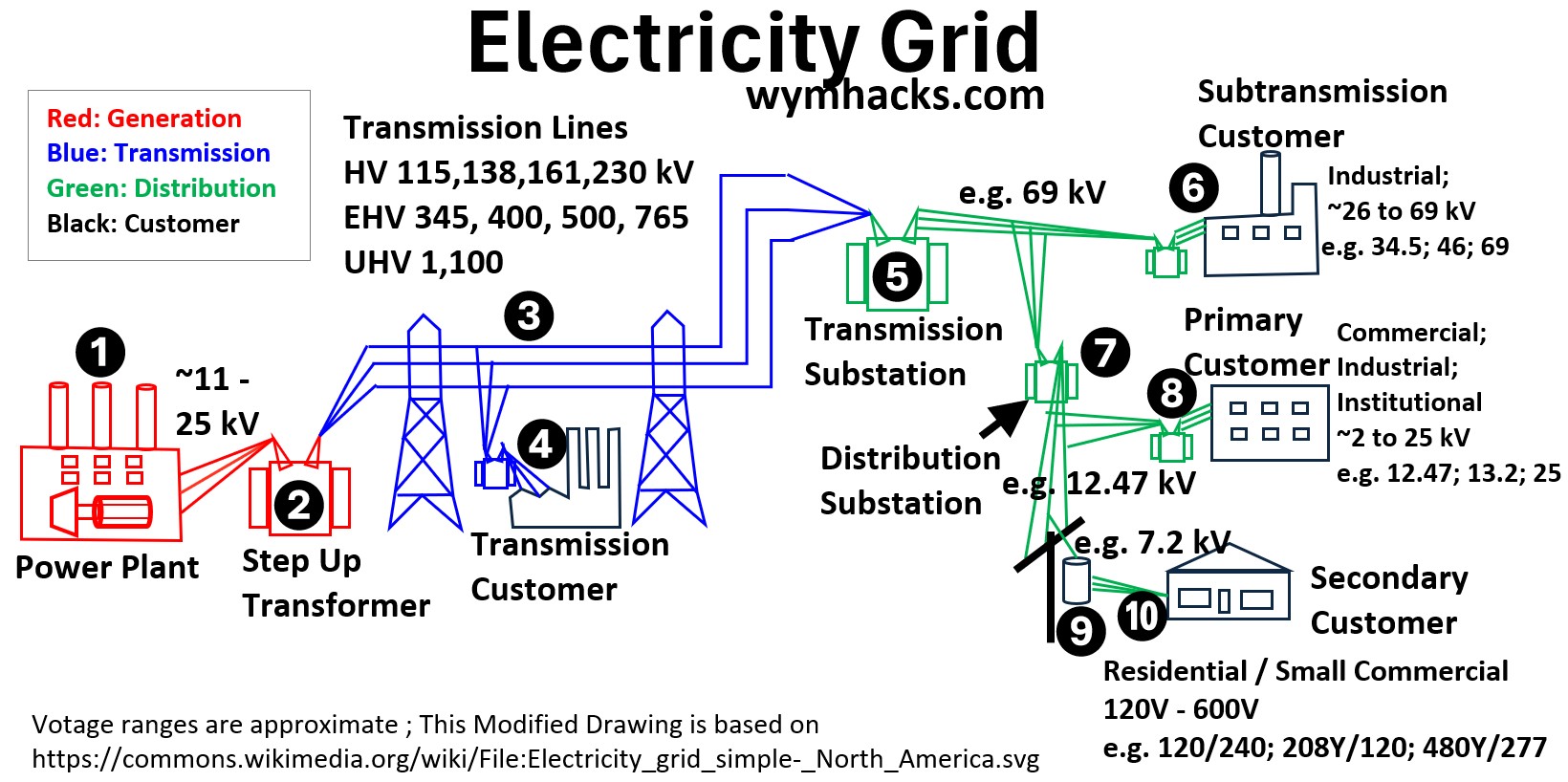
The picture below displays a “typical” electrical distribution system.
The essential first step in this process is the generation of power (location #1 in the picture below).
Picture: Electricity Grid
The generating station is where electricity is produced.
Using various forms of energy, a magnetic shaft is rotated inside a conducting coil, which captures and transfers the generated electricity.
Large facilities, like
- power plants (using nuclear, coal, natural gas to provide water boiling heat),
- hydroelectric dams, and
- solar/wind farms and
- others
convert primary energy sources into electrical energy.
The generating stations (#1 in the drawing above) in these facilities create high-voltage alternating current (AC) power, often at ~ 11 kV to 25 kV (kV is thousands of Volts) .
This is the starting point of all power flowing through the grid.
In this article, we will focus specifically on the principles of alternating current (AC) electrical generation.
Faraday’s Law and Magnetic Flux
Faraday’s Law
According to Faraday’s Law of Induction, the induced EMF ( or ) in a coil is proportional to the rate of change of magnetic flux () through the coil:
- is the number of turns in the coil.
Magnetic Flux
Picture: Magnetic Field B and Magnetic Flux
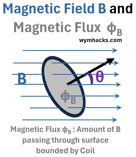
Magnetic flux , ΦB , is the measure of a magnetic field passing through a surface.
The magnetic flux through a single loop of area in a uniform magnetic field is given by:
(2) ΦB = Magnetic Flux = (B)(Ap) =BAcos(θ) = B̄•Ā ; for Uniform B and Flat Surface where
- ΦB = magnetic Flux (units: (N/C)m2)
- Ap (units: m2) = Perpendicular component of A that the magnetic field passes through.
- B = The magnetic field (units: N/C)
- B̄•Ā = dot product of the magnetic field vector and the area vector.
- θ = angle between area vector and B vector
Rotating Coil in a Fixed Magnetic Field
In order to understand how a large power plant electric generator works, we need to start with a simplified model of a conducting coil rotating in a fixed magnetic field.
note: The drawing below and the associated concepts are based on Mahesh Shenoy’s fantastic Khanacademy video: EMF & flux equation (& graph) of AC generator.
Check out the awesome picture below where we have
- a conducting coil (green colored paddle shaped figure in the drawing below)
- rotating in a fixed magnetic field (brown field lines going from left to right)
Picture: Rotating Coil in a Stationary Magnetic Field – AC Generator
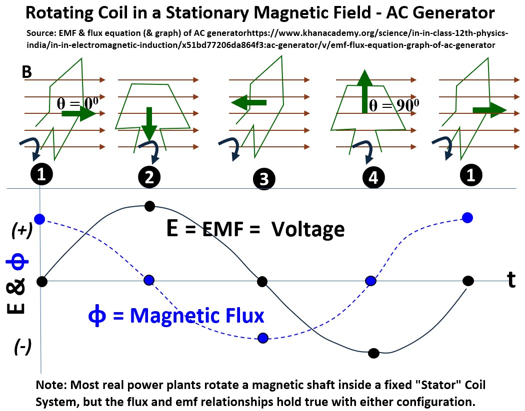
In the picture above
- A coil is being rotated in a constant magnetic field B where
- θ = is the angle between B and
- the Area Vector (the green arrow situated perpendicular to the flat surface of the coil) .
- A plot of Magnetic flux Φ and EMF (E or Voltage) vs time is generated with each 90 degree rotation of the coil.
Alternating Current (AC)
The voltage (EMF) curve you see on the graph is a direct reflection of the coil’s physical position relative to the magnetic field.
Because the coil rotates at a constant speed, the rate at which it “cuts” through magnetic flux follows a smooth, repeating cycle.
If you connect this system to a circuit, the current will display the same sinusoidal behavior as the voltage.
This means the electrons do not simply flow in a circle;
- instead, they accelerate, slow down, stop, and reverse direction
- in perfect synchronization with the rising and falling wave as shown on the graph.
This synchronized rising and falling is the defining characteristic of Alternating Current (AC).
Unlike Direct Current (DC), which provides a constant “push” in one direction, AC uses the sinusoidal motion of the generator to oscillate energy back and forth.
In the graph above, when the curve crosses the horizontal center line,
- the current is momentarily zero as it prepares to change direction.
- The peaks and valleys represent the moments of maximum flow in opposite directions.
This efficient, wave-like delivery of power is what allows electricity to be transmitted over long distances to reach our homes and businesses. (see the section “But Why AC” for more on this).
Ok we are getting a little ahead of ourselves.
We’ll come back to these concepts, but let’s look at a few equations first.
Magnetic Flux and Voltage for a Rotating Coil in a Constant Magnetic Field
Ok, lets pull up that beautiful rotating coil picture again and go through each sequence and apply our two key equations for flux and voltage.
Remember that,
(2) ΦB = Magnetic Flux = (B)(Ap) =NBAcos(θ); for N coils, Uniform B and Flat
Also remember that:
sine (00)= 0 ; sine(900) = 1
cos(00) = 1 ; cos(900) = 0
Picture: Rotating Coil in a Stationary Magnetic Field – AC Generator
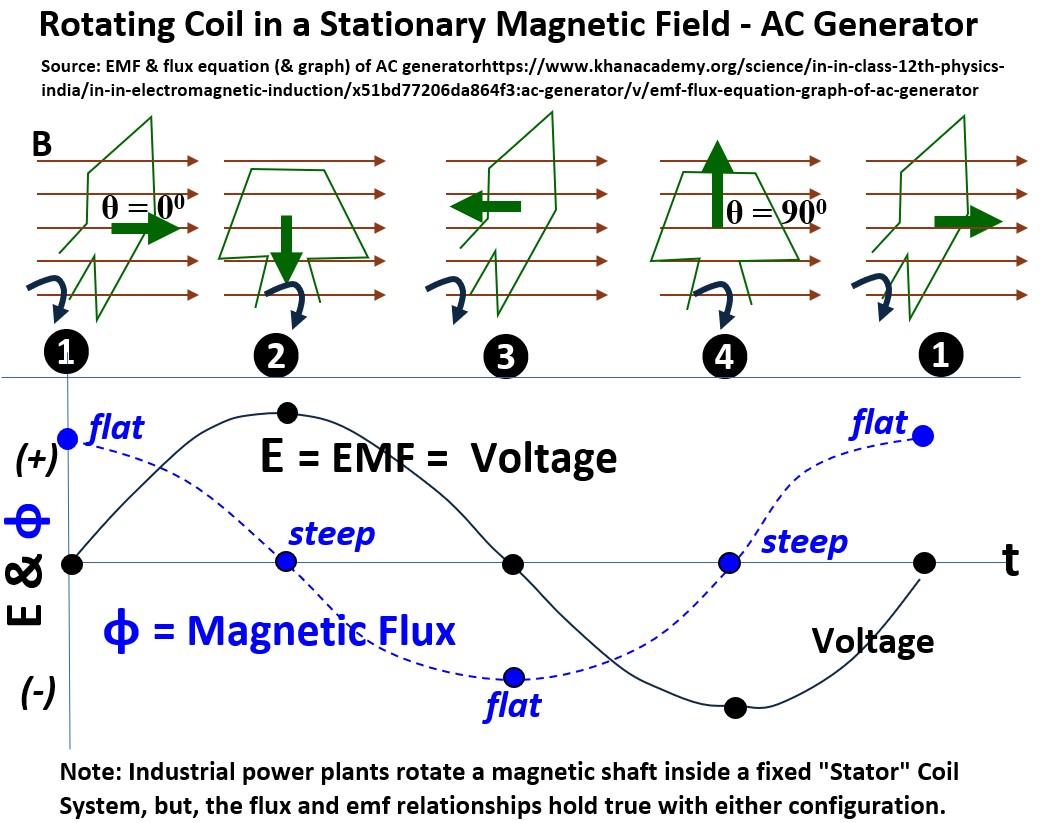
Position 1
- θ = 0
- ΦB = NBAcos(0) = NBA(1) = ΦBmax
Was that intuitive that the voltage would be zero at maximum flux? Not to me.
But, the flux curve and Faraday’s law helps us understand this.
At position 1,
- the magnetic flux curve, at its peak, is “flat” and
- “flat” means that the slope, is zero
Position 2
- θ = 90
- ΦB = NBAcos(90) = NBA(0) = 0
The flux curve and Faraday’s law explains why voltage is at a maximum.
At position 2,
- the magnetic flux curve is at its “steepest” and
- “steepest” means that the slope, is at a maximum,
Position 3
- θ = 180
- ΦB = NBAcos(180) = NBA(-1) = -ΦBmax
The flux curve and Faraday’s law show why voltage is 0.
At position 3,
- the magnetic flux curve is “flat” and
- “flat” means that the slope, is 0,
Position 4
- θ = 270
- ΦB = NBAcos(270) = NBA(0) = 0
The flux curve and Faraday’s law show why voltage is a negative maximum.
At position 4,
- the magnetic flux curve at position is “steepest”, and
- “steepest” means that the slope, is at a maximum,
Modern Power Plants: Flipping The Model
In the previous sections we described electromagnetic induction using the model of a rotating conducting coil in a stationary magnetic field.
What if we flip our model around and let the magnetic field move and keep the coil stationary?
Does anything change with respect to all the phenomena we saw and explained above?
No!
Faraday’s law still holds and voltage (current also) over time will graph sinusoidally.
In the drawing below, I show a rotating magnetic field (From A to B to C to D) and a stationary conducting coil with a certain planar area (the blue circle in the drawing below).
Picture: Fixed Coil and Rotating Magnet Field
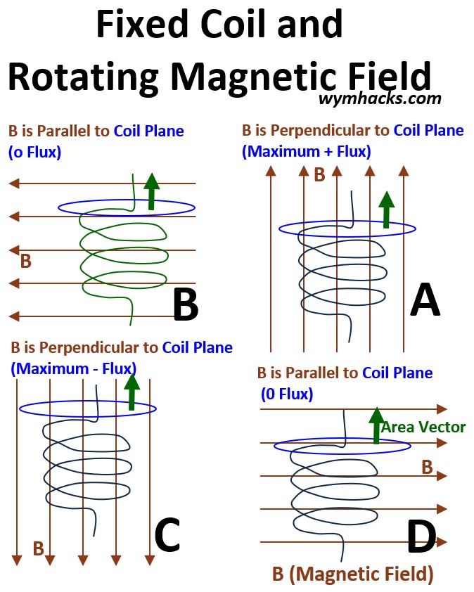
And remember, max flux means zero voltage and vice versa.
The output will still be sinusoidal voltage and flux values over time.
This is a very good thing because the actual physical configuration of an electric power generator in a power plant employs this configuration: i.e. a rotating magnetic shaft inside a stationary conducting coil.
They are designed this way because it is much safer and more efficient to handle very large amounts of electricity.
While small generators (like those displayed in a science classroom or modelled in a Khanacademy tutorial) often spin a coil inside a magnet, doing this at a power plant scale presents engineering challenges.
High-Voltage Handling
The electricity generated in a power plant is high-voltage (often 11,000V to 33,000V).
- If the coils were spinning, you would need massive, sliding metal rings called slip rings to transfer that power to the grid.
- These rings would spark, wear out almost instantly, and be nearly impossible to insulate at those voltages.
- By keeping the coils stationary, they can be bolted directly to the output cables.
Weight and Centrifugal Force
The “armature” (the coils where power is produced) is the heaviest part of a generator because of the massive amount of copper and steel required.
- Spinning this heavy mass at high speeds (e.g., 3,600 RPM) creates enormous centrifugal forces that could tear the machine apart.
- It is much easier to spin the lighter magnetic shaft and keep the heavy copper coils securely anchored in the outer frame.
Cooling Efficiency
Power plant generators generate intense heat.
- Because the stator (stationary part) doesn’t move, engineers can easily run complex cooling systems through it—
- such as pipes filled with water
- or pressurized hydrogen gas—to keep the copper coils from melting.
- Cooling a rapidly spinning part is significantly more difficult.
Mechanical Simplicity
To create the magnetic field, you only need a small amount of low-voltage DC electricity.
- This small current can be safely transferred to the rotating shaft using small, simple slip rings.
- It’s a “best of both worlds” scenario:
- you spin the part that needs very little power and
- keep the part that handles the “heavy lifting” stationary.
Single Phase AC Generator
Now, let’s imagine we have a simple electric generator set up as shown in the picture shown below.
- We have a single magnetic arm or stick (with it’s North and South poles) which is allowed to rotated between two connected and fixed coils.
- The coils are placed at 12 o’clock and 3 o’clock in the drawing.
- We connect the coil to a load (a lightbulb for example).
As the magnetic stick rotates counterclockwise from 4 to 3 and back to 4 in the drawing, a voltage is produced and displays as a sinusoidal graph of velocity over time (or angle).
Picture: Single Phase Generator
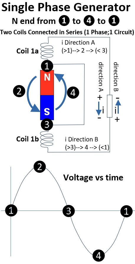
Position_1
- Magnet N at 12 o’clock
- Magnetic flux is at a maximum
- Voltage is zero
- From 1 to 2, Voltage rises and
- Current is in direction A
Position_2
- Magnet N at 9 o’clock
- Magnetic flux is zero
- Voltage is at a maximum
- From 2 to 3, Voltage drops and
- Current is in direction A
Position_3
- Magnet N at 6 o’clock
- Magnetic flux is maximum
- Voltage is zero
- Current direction reverses to B
- From 3 to 4, Voltage increases in magnitude
Position_4
- Magnet N at 3 o’clock
- Magnetic flux is zero
- Voltage is at a maximum magnitude
- From 4 to 1, Voltage magnitude drops and
- Current is in direction B
This reversal of voltage (and current) is why we call this Alternating Current or AC electricity.
So, we see that a single pair of coils generates a single-phase current, characterized by a single voltage wave.
By expanding the setup to a three-pair configuration, we create three distinct voltages.
Picture: Three Phase Generator Simple Schematic
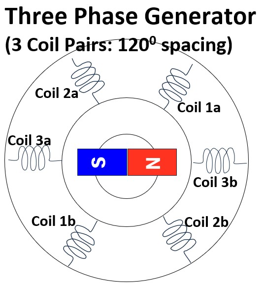
Because these coils are physically offset, they produce three separate ‘phases’ of electricity that work together to provide more consistent power.
In the picture above, it’s assumed that the like numbered coils are connected.
I like Michel Van Biezen’s rendition of the above which is shown below (same thing).
You should watch these great Van Biezen videos on this topic.
- Electrical Engineering: Ch 13: 3 Phase Circuit (3 of 42) A 3 Phase Generator (3 Coil)
- Electrical Engineering: Ch 13: 3 Phase Circuit (4 of 42) A 3 Phase Generator (6 Coil)
Let’s continue now with a discussion of three phase power generation.
Three Phase AC Generator Concept
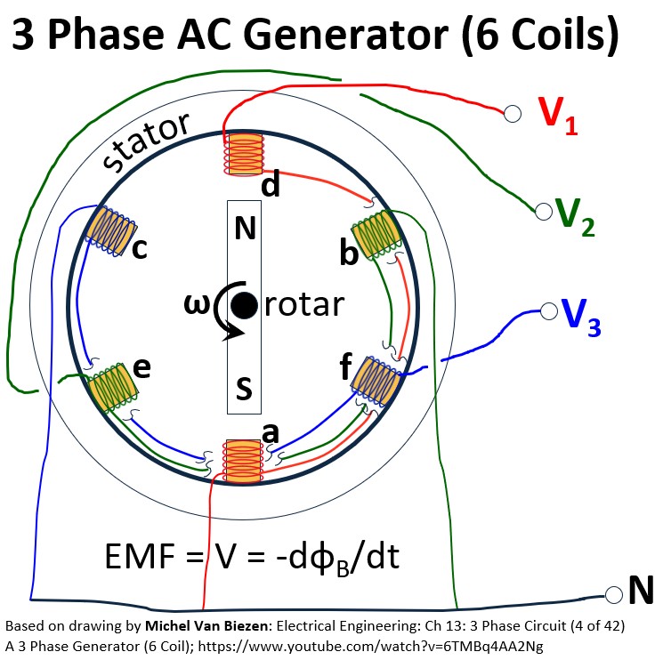
Ok, let’s redraw that 3 coil , 6 pair arrangement (Coil pairs A, B, C).
See the awesome drawing below:
- The coil pairs A, B, C are serially connected (e.g. A1 connected to A2 etc.)
- Each coil can be identified as a start (1) and a return (2)
- The physical locations of each coil pair are offset from the others by 120 degrees
- A chart of voltage versus angle can be generated as the magnet moves counterclockwise starting from location a
Picture: 3 Phase AC Generation (120 degree “separation”)
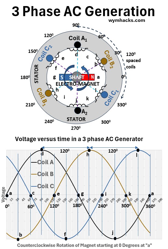
The Starting Position
At the start (3 o’clock), the magnet North pole is positioned halfway between the A1 (12 o’clock) and A2 (6 o’clock) bundles.
- At 3 o’clock, the magnet is “neutral” relative to Phase (Coil) A and no voltage is generated.
- We are assuming the “coil opening plane” is perpendicular to the magnetic field lines
- So the magnetic flux is maximized, and
- therefore the voltage is zero (see the earlier sections for a more detailed explanation of why)
Generating the Waves (The 120° Sequence)
As the magnet moves counterclockwise, the North pole begins its journey around the circle.
From 0° to 90° (3 o’clock → 12 o’clock; a → d)
- The North pole approaches A1 and
- The magnetic flux starts dropping.
- The voltage in Coil (Phase) A climbs to its positive peak as the pole passes directly under the A1 bundle at 12 o’clock (where flux is now zero).
Reaching Phase B (120° later from A1; d → h)
- Because the B1 bundle is physically located 120° counterclockwise from A1,
- the magnet has to travel exactly one-third of a circle before phase B reaches a maximum voltage.
Reaching Phase C (120 from B1; h → l)
- The magnet continues to the C1 bundle.
- By the time the voltage peaks here, it has traveled two-thirds of the circle.
Phase Concept
In a 2 magnetic pole machine (one N, one S), the mechanical degrees and electrical degrees are identical.
- If you move the magnet 120 physical degrees, you move the electricity 120 electrical degrees.
The Electrical Phase (Timing) essentially means “delay.”
- Because the magnet cannot be in two places at once, it interacts with each coil at a different time.
- This results in three separate voltage waves that are “out of step” with each other.
The Return Bundles (A2, B2, C2)
While the North pole is peaking the “1” bundles (A1, B1, C1), the South pole is simultaneously passing the “2” bundles (A2, B2, C2) on the opposite side of the stator.
- This doubles the strength of the voltage in that phase because both sides of the coil loop are being “pushed” by a magnetic pole at the same time.
Why 3-Phase is Better than Single-Phase
Constant Power Delivery
- In a single-phase system, the voltage crosses zero twice every cycle, meaning there are brief moments where no power is being delivered.
- In a three-phase system, the waves are offset by 120 degrees; when one phase is at zero, the other two are always active.
- This results in a continuous, smooth flow of power.
Material Efficiency
- To transmit the same amount of power, a three-phase system requires significantly less conductive material (copper or aluminum) than a single-phase system.
- You can essentially deliver nearly twice the power using only one additional wire.
Superior Motors
- Three-phase power naturally creates a rotating magnetic field.
- This allows industrial motors to be simpler, smaller, and self-starting.
- Single-phase motors usually require extra components like capacitors or starter windings to get moving and are prone to vibration because their power pulses.
Why we don’t use 4, 6, or 12 phases
While adding more phases is technically possible, we don’t do it for distribution because of the Law of Diminishing Returns:
Complexity vs. Gain
- Moving from 1 phase to 3 phases provides a massive leap in efficiency and motor performance.
- However, moving from 3 phases to 6 phases provides only marginal improvements in smoothness
- while doubling the number of wires, circuit breakers, and transformer windings required.
Infrastructure Cost
- Every additional phase requires another set of heavy cables on every utility pole and more complex hardware at every substation.
- The cost of building and maintaining a 6-phase grid would be astronomical for very little practical benefit.
Note: We actually do use higher phases (like 6 or 12) in very specific niche applications (e.g. high-voltage DC (HVDC) transmission).
See these Great Videos on three phase AC from Paul Evans at Engineeringmindset.com
- How 3 Phase Power works: why 3 phases? – Engineering Mindset
- Three Phase Electricity Basics and Calculations electrical engineering – Engineering Mindset
- How Three Phase Electricity works – The basics explained – Engineering Mindset
This one by Jim Pytel is great also.
But Why AC?
We explained why three phase AC is more efficient that single phase AC but why AC itself. Why not use DC for example?
In an earlier section I mentioned that AC is the most efficient form of electricity for long distance transfer.
Here’s why.
The efficiency of Alternating Current (AC) for power transmission comes down to one key device: the transformer.
The Transformer
A transformer is a stationary electrical device that transfers energy between two or more circuits through electromagnetic induction.
It consists of two coils of wire (the primary and secondary windings) wrapped around a common iron core;
- when an alternating current flows through the primary coil,
- it creates a fluctuating magnetic field
- that induces a voltage in the secondary coil.
In a power plant three phase step up transformer, like the one in the drawing below, there will be three sets of primary and secondary windings that are wrapped around a central core.
Picture: Typical Look of a Step Up or Step Down Three Phase Transformer
![]()
Or we could have a much simpler design like in a typical single phase transformer that feeds you house.
This has the typical “can” shape you see hanging from utility poles in your neighborhood.
Inside this “can” there will be a primary and a secondary coil wrapped around an iron core.
Picture: Typical Look of a Single Phase Step Down Transformer that Feeds your house
![]()
Without the transformer, electrical transmission and distribution systems (that get electricity to your house) would not work.
- Voltage Conversion: It allows us to
- “step up” voltage to extremely high levels for long-distance travel and
- “step down” to safe levels (like 120V) for your wall outlets.
- Massive Efficiency: By increasing voltage,
- the transformer drastically reduces the current.
- Since heat loss in wires is caused by current, this allows us to move power over very long distances very little energy wasted.
Transformers – working & applications (step up and step down) – Khanacademy
The Power of “Stepping Up”
The most efficient way to move electricity is at super-high voltage and low current.
According to Joule’s Law (P = I2R),
- the energy lost as heat is proportional to the square of the current.
By using a transformer to “step up” the voltage, we can drop the current significantly, which drastically reduces the amount of energy wasted as heat in the transmission lines.
Why Only AC?
Transformers rely on electromagnetic induction, which requires a constantly changing magnetic field to work.
Because AC current is always oscillating (the sinusoidal wave we’ve been graphing), it naturally creates this changing field.
Direct Current (DC) stays at a constant level, so it cannot be easily stepped up or down with simple, inexpensive transformers.
Practical Distribution
Once the high-voltage electricity reaches your neighborhood, another transformer “steps down” the voltage to a safe, usable level (like 120V or 240V).
This ability to cheaply and easily transform voltage levels at both ends of the wire is why AC became the global standard for the power grid.
Picture: Electricity Grid Uses Alternating Current to Step Up and Step Down Electricity
![]()
Components of a Real Power Plant Electrical Generator
Ok, what do we know so far?
- Inside a generator, there are three separate sets of copper coils (windings) fixed in a circle, spaced exactly 120 degrees apart.
- A central magnet (the rotor) is spun by an external force, like a steam turbine or a wind blade.
- As the magnet’s North and South poles sweep past each coil in sequence, they push and pull electrons through the wires.
- Because the coils are physically offset by 120 degrees, the three resulting “pulses” of electricity reach their peak strength at different times, creating the three distinct phases of power.
Essentially, you are taking a single mechanical rotation and harvesting it three times over, resulting in the continuous, overlapping flow of energy that makes the grid so stable.
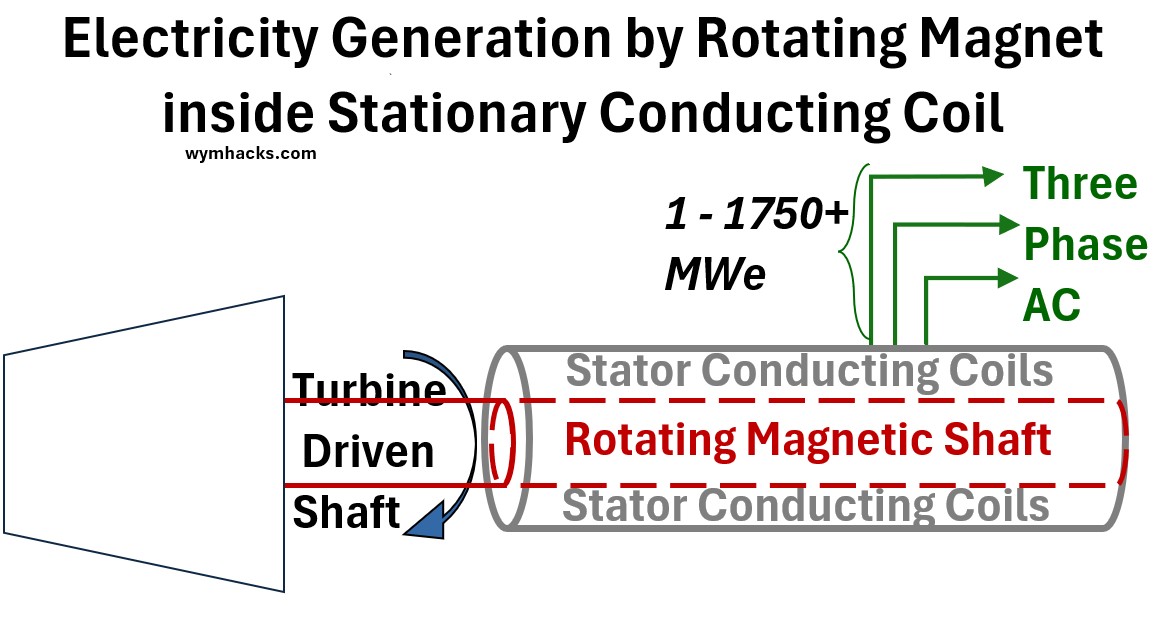
A very simplified schematic for an electric generator is given below where I show
- a turbine (a steam driver) connected to a
- shaft which, inside the electric generator, is connected to a magnet (or magnets).
- This magnet then rotates with the shaft rotation and induces electricity generation in circumferential stationary conducting coils.
Picture: Simplified Electric Generator Schematic
A Real Large Power Plant Electric Power Generator is a Complicated Mechanical Marvel
Industrial-size generators at power stations are massive, sophisticated machines designed for continuous, high-output operation.
These generators, as generally represented above, use a stationary armature (conducting coil) and a rotating magnetic field to manage the extreme voltages and currents.
In reality, one of these machines in a large power plant might look like the Siemens electric generator shown below.
- It’s Big!
- This whole package is roughly 4.2 – 4.5 m wide or tall (14 to 15 feet) and
- about 10 to 12 meters long (about 33 to 40 feet)!!
The Siemens SGen-3000W series is a world-class Synchronous Generator.
- It’s designed to generate power often exceeding 1,000 MW (1 GW) when coupled with large steam or gas turbines.
Picture: Example of a Very Large Industrial Electric Generator
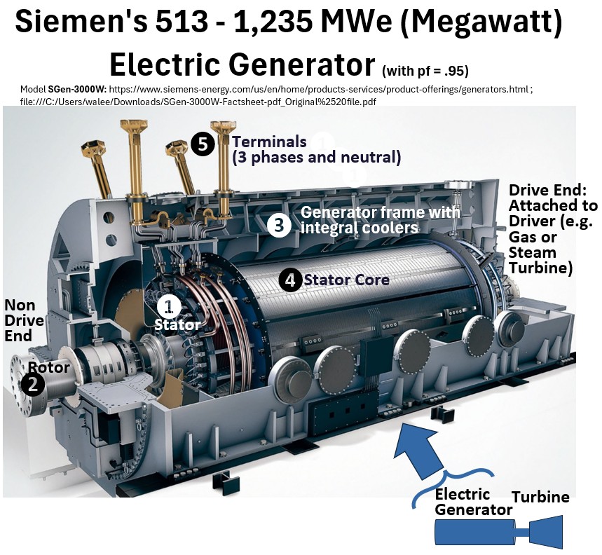
I think it’s instructive to get into some of the details.
Keep in mind that , although the actual mechanical layouts are very sophisticated, the principles shown in the earlier tutorial graphics are all still valid.
Prime Mover
- This is the “muscle” that spins the generator.
- In a power plant, this is typically a steam turbine, gas turbine, or hydroelectric turbine.
- It provides the mechanical energy required to rotate the internal components at a precise, constant speed.
The Rotor (Field)
- The central rotating shaft of the generator will have magnetic coils attached to it.
- In large industrial units, this whole unit (shaft plus magnetic coils) is a rotating electromagnet.
- It is fed with a small amount of DC current to create a powerful magnetic field that spins at high speed (e.g., 3,600 RPM for 60Hz power).
- In a massive machine like the Siemens SGen-3000W, the rotor is divided into two distinct functional ends:
- the Drive End (DE) and the Non-Drive End (NDE).
- The Drive End is the heavy-duty mechanical interface that is physically coupled to the steam or gas turbine to receive the rotational energy, while
- the Non-Drive End (or “free end”) houses the excitation equipment,
- such as the collector rings or brushless exciter, and
- is supported by a bearing designed to allow the rotor shaft to safely expand lengthwise as it heats up.
- To get the generated power out of the machine and into the grid, the stator windings are connected to Main Terminals (usually located in a large terminal box on the bottom or side of the generator frame),
- where the electricity is routed through massive isolated phase bus ducts (IPB) to a step-up transformer that prepares the power for high-voltage transmission.
The Exciter
- Large generators cannot use permanent magnets because they are too heavy and their strength cannot be adjusted.
- Instead, an “exciter” (essentially a smaller generator mounted on the same shaft) provides the DC current to the main rotor to create its magnetic field.
- It’s not labeled in the drawing but it will be located on the shaft on the none drive end.
Synchronous Speed (N)
This is not really a component, more of a property attributed to a component. It’s pretty important so I’ll talk about it here.
The main equation for an electric generator’s shaft speed (RPM) links it to the output frequency (Hz) and the number of magnetic poles, typically expressed
N = (120 × f) / P = synchronous speed needed to generate a specific electrical frequency (with the actual speed slightly lower under load due to slip).
N = (f cycles/s)(60 s/min)(2 poles/cycle)(1 revolution/P poles)
Where
- N: Shaft speed in Revolutions Per Minute (RPM).
- f: Frequency of the electrical output in Hertz (Hz).
- P: Number of magnetic poles in the generator.
- 120: A constant (60 seconds/minute × 2) to convert units.
Example:
The Siemens SGen-3000W is a 2 pole machine meaning at 60 Hz the RPM will be
- Synchronous Speed in RPM = (60)(120)(1/2) = 3600 RPM
- Note, If this machine were a 4 pole machine (i.e. essentially 2 magnets on the rotor), then RPM = 1800 RPM
The Stator (Armature)
- The stator is the heavy outer frame and core of the generator, the part you see when looking at the large cylindrical body.
- Stator Core: This is made up of thin, stacked silicon steel laminations.
- This material and lamination process minimizes energy loss from eddy currents and hysteresis as the magnetic field sweeps past.
- Stator Windings (Armature):
- These are the conductors (massive, insulated copper bars) fitted into the slots of the core.
- These windings are connected in a three-phase Wye (Star) configuration and are where the electrical power is induced and then delivered to the grid (via the four terminals).
The Windings are actually Bars not Coils
While the operating principle involves the same 120-degree spatial phasing found in simple motors,
- these “coils” are actually massive, rigid stator bars composed of dozens of transposed copper strands—some of which are hollow to allow for internal water cooling.
- Rather than loose wire, they are wrapped in layers of mica-based insulation and vacuum-impregnated with resin to form a rock-hard, high-voltage assembly.
- These bars are meticulously woven into a complex “basket” at the ends of the generator, ensuring the physical geometry precisely maintains the three-phase electrical offset required to generate balanced power.
Cooling System
- The Siemens SGen-3000W utilizes a specialized dual-cooling system to manage the immense heat generated by its 1,300 MVA output.
- The stator is directly cooled by demineralized water flowing through hollow copper conductors.
- The rotor spins in a pressurized hydrogen gas environment;
- hydrogen is used because it is much less dense than air—reducing “windage” friction losses—
- and has a significantly higher thermal conductivity,
- allowing it to pull heat away from the spinning components far more effectively than a standard air-cooled system.
Control & Protection
- An Automatic Voltage Regulator (AVR) acts as the “brain,”
- constantly adjusting the exciter’s output to
- ensure the generator maintains a steady voltage even as the city’s power demand fluctuates.
The Switchyard
Before the power leaves the station, it passes through
- massive circuit breakers and
- Step-up Transformers that boost the voltage to hundreds of thousands of volts for efficient long-distance travel.