Single Phase AC Power Triangle
The equations derived in the previous sections—specifically P = VrmsIrmscos(Φ) and P = √3VLILcos(Φ)—all solve for Active (or Real or True) Power (P).
While these formulas give us the numerical value of the work being done, it is important to remember that they represent only one side of the electrical story.
In an AC circuit, Active Power is the “Real” power.
It is the energy that is permanently consumed by the load and converted into useful output, such as
- the rotation of a motor shaft,
- the heat of an element, or
- the light from a bulb.
However, because most AC systems rely on magnetic fields to operate (like the windings in a motor or transformer), there is a second type of “power” at play that doesn’t show up in our P equations: Reactive Power.
Any single phase AC circuit, no matter how complicated, can be described with a power triangle and it looks like the picture below.
We reviewed this in depth in my post AC Circuits: I-V Relationships, Impedance, Admittance, and Power
Picture: Power Triangle For Single Phase AC System
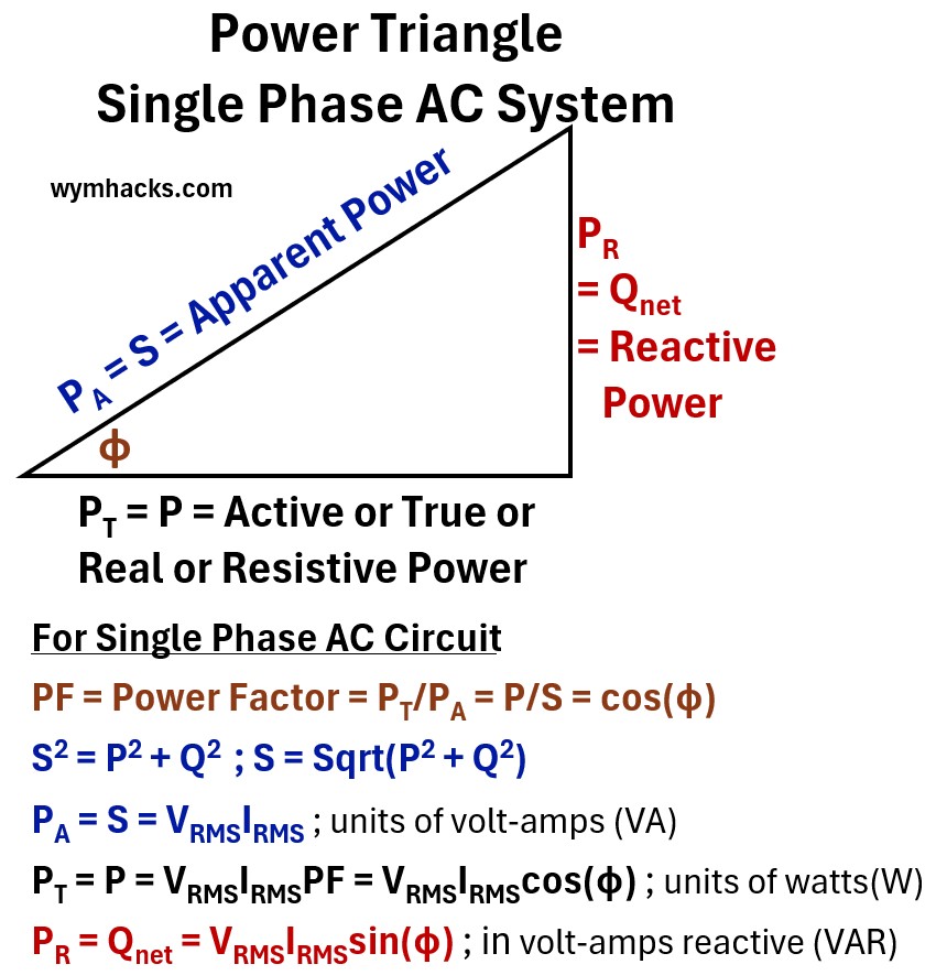
where
PA = S = Apparent Power
- The total “theoretical” power delivered to a circuit, representing the product of voltage and current without considering the timing difference between them
PT = P = Active / True / Real / Resistive Power
- The actual power that performs useful work or generates heat, representing the portion of energy truly consumed by the load.
PR = Qnet = Reactive Power
- The “non-working” power that oscillates back and forth between the source and the load to maintain magnetic or electric fields.
φ = phase angle
- Angular difference between the Voltage sine wave and the Current sine wave.
- The displacement in time, measured in degrees or radians, between the peaks of the voltage and current sine waves.
PF = Power Factor = PT/PA = P/S = cos(φ)
- A ratio between 0 and 1 that represents the efficiency of power usage, calculated as the fraction of apparent power that is converted into real work.
S2 = P2 + Q2 ; S = Sqrt(P2 + Q2)
- The geometric relationship based on the Pythagorean theorem showing that apparent power is the vector sum of real and reactive power.
PA = S = VRMSIRMS ; units of volt-amps (VA)
- The formula for total power capacity measured in volt-amps (VA), calculated by multiplying the effective voltage and current.
PT = P = VRMSIRMSPF = VRMSIRMScos(φ) ; units of watts(W)
- The formula for the actual wattage consumed, which scales the total power by the efficiency of the phase alignment.
PR = Qnet = VRMSIRMSsin(φ) ; in volt-amps reactive (VAR)
- The formula for the reactive power measured in VAR, representing the component of power that is 90 degrees out of sync with the voltage.
VRMS = Root Mean Square Voltage
- The effective AC voltage value that produces the same heating effect as an equivalent DC voltage.
IRMS = Root Mean Square Current
- The effective AC current value representing the steady-state equivalent flow of charge over time.
RMS = Root Mean Square
- A mathematical method used to calculate the “effective” magnitude of a varying waveform, like a sine wave.
- See my post: RMS (Root Mean Square) of a Sinusoid
Let’s now construct the power triangle for a three phase AC balanced circuit.
The Three-Phase AC Power Triangle
Moving from a single-phase understanding to a three-phase system is a logical progression.
Think of it as moving from a single engine cylinder to a perfectly timed three-cylinder engine.
Here is the step-by-step sequence to bridge that gap.
Step 1: Define the Balanced 3-Phase Set
In a balanced three-phase system, you have three separate “phases” (A, B, and C).
Each phase behaves exactly like a single-phase circuit, but they are mathematically offset:
- Each phase has the same RMS Voltage and RMS Current.
- Each phase is shifted by 120° from the others.
- Each phase has the exact same Power Factor cos(Φ).
Step 2: Calculate Total Real Power (P)
Since the system is balanced, the total real power is simply the sum of the power in each of the three phases.
Note we did the same thing the “three Phase AC Power Derivations” section above.
- Power of one phase: Pph = (Vph )(Iph )(cos(Φ))
- Total Power: P = 3(Vph )(Iph )(cos(Φ))
Step 3: Relate Phase Values to Line Values
In the real world, we usually measure Line Voltage (VL) and Line Current (IL) because those are the terminals we can actually access.
Depending on the connection (Wye or Delta), a √3 factor appears: (see the “three Phase AC Power Derivations” section for how)
- In Wye (Star): VL = √3 (Vph ) and IL = Iph
- In Delta: VL = Vph and IL = √3 (Iph )
Step 4: Substitute and Simplify
Whether the system is Wye or Delta, when you substitute the Line values back into the total power equation
- PTotal = 3(Vph)(Iph)cos(Φ), the math results in the same constant:
- P = √3VL ILcos(Φ); (as we showed in the “three Phase AC Power Derivations” section)
Step 5: Apply the Same Logic to Q and S
Because the phase shifts and magnitudes are identical for reactive and apparent power, the √3 constant applies to them as well:
- Reactive Power: Q =√3VLILsin(Φ)
- Apparent Power: S = √3VLIL
Step 6: Construct the 3-Phase Power Triangle
Now, take these three new values (P, Q, S) and place them back into the triangle.
- The horizontal leg is P (Total Watts).
- The vertical leg is Q (Total VAR).
- The hypotenuse is S (Total VA).
The relationship S2 = P2 + Q2 remains perfectly intact because you have scaled every side of the triangle by the same factor
- 3 relative to phase values, or √3 relative to line values).
And voila, we see that we can derive a three phase power triangle which is simply a scaled up version of its single phase triangle.
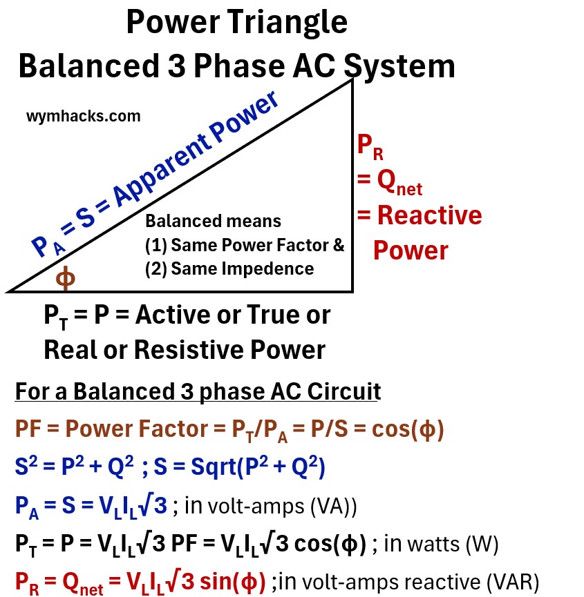
where
PA = S = Apparent Power
- Apparent Power (PA or S): The hypotenuse, measured in volt-amperes (VA).
- This is the total power that the wires, transformers, and generators must be sized to carry.
- PA= S = √(P2 + Q2)
PT = P = Active / True / Real / Resistive Power
- The base of the triangle, measured in watts (W).
- This is the horizontal component that performs actual work.
- P = PT = (S)cos(Φ)
PR = Q = Qnet = Reactive Power
- The vertical side, measured in volt-amperes reactive (VAr….or VAR).
- This power oscillates between the source and the load to maintain magnetic fields.
- it performs no actual work but is necessary for the system to function.
- Q = Qnet = PR = (S)sin(Φ)
φ = phase angle
- Angular difference between the Voltage sine wave and the Current sine wave.
PF = Power Factor = PT/PA = P/S = cos(φ)
- The Power Factor tells us how efficiently the system is converting the total supplied energy into useful work.
S2 = P2 + Q2 ; S = Sqrt(P2 + Q2)
PA = S = √3VLIL ; units of volt-amps (VA)
PT = P = √3VLILPF = √3VLILcos(φ) ; units of watts(W)
PR = Qnet = √3VLILsin(φ) ; in volt-amps reactive (VAR)
Line terminals
- In a three-phase system, VL and IL refer to the measurements taken at the “Line” terminals
- They are the actual wires connecting the source to the load.
VL = RMS Line Voltage
IL = RMS Line Current
- RMS = Root Mean Square
- A mathematical method used to calculate the “effective” magnitude of a varying waveform, like a sine wave.
- See my post: RMS (Root Mean Square) of a Sinusoid
The Conclusion
The “geometry” of the triangle does not change when moving from single-phase to three-phase.
The only thing that changes is the scaling factor.
You are effectively stacking three identical single-phase triangles together to form one larger, balanced 3-phase triangle.
Let’s Get Clear on Electric Power Units of Measure
While the power triangle distinguishes between Active, Reactive, and Apparent power to highlight their different roles in a circuit, they all share the same fundamental physical dimension: energy per unit time.
Because power is the product of voltage and current, the basic unit for all three is technically the watt (1 W = 1 Joule/second).
However, to avoid confusion and clearly signal which component of the power triangle is being discussed, engineers use distinct labels:
- Watts (W) are reserved for Real or Active power (P or PT ),
- Volt-amperes reactive (VAR or VAr) are used for Reactive power (Q = Qnet = PR), and
- Volt-amperes (VA) denote Apparent power (PA = S).
Picture: Electrical Power Units of Measure
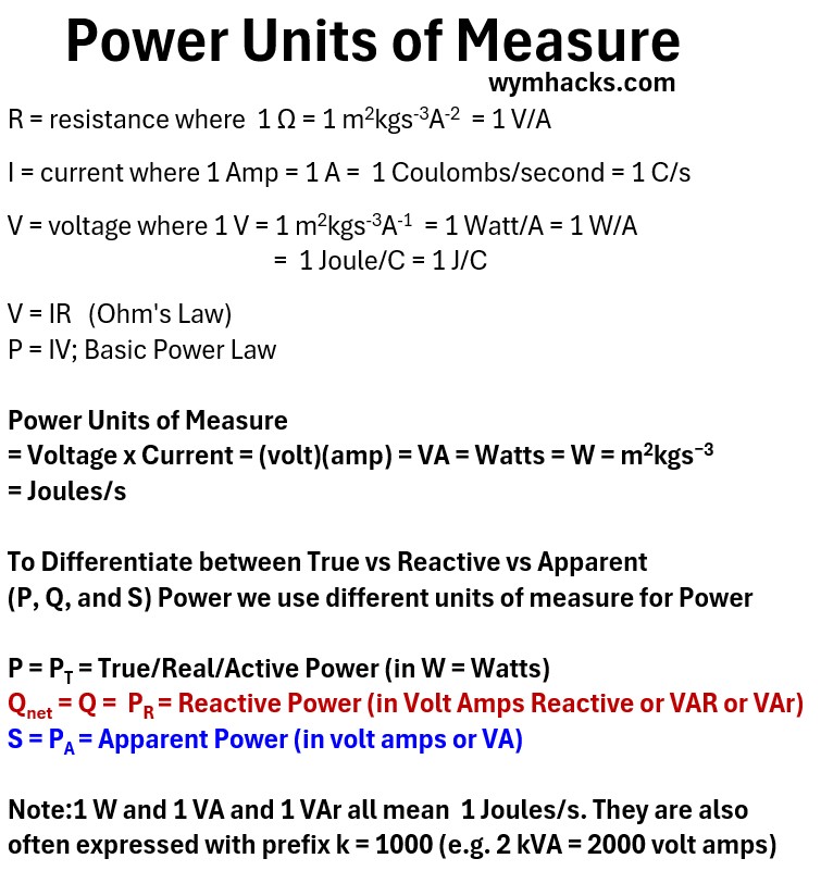
In industrial and utility-scale applications, the quantities involved are so large that the metric prefix “k” (kilo) is standard, resulting in kW, kVAR (or kVAr), and kVA (representing 1,000 units each).
This shorthand allows professionals to instantly recognize whether a measurement refers to the
- power performing actual work,
- the “magnetizing” energy oscillating in the system, or
- the total combined burden on the electrical infrastructure.
Electrical Power Analogies: Beer vs. Physics
To help conceptualize why we have “extra” power that doesn’t do work, we can look at two common analogies.
One simple but flawed analogy is the beer glass with foam on top.
The other is a more accurate analogy of a horse pulling a rail car at an angle.
Picture: Power Triangle Analogies
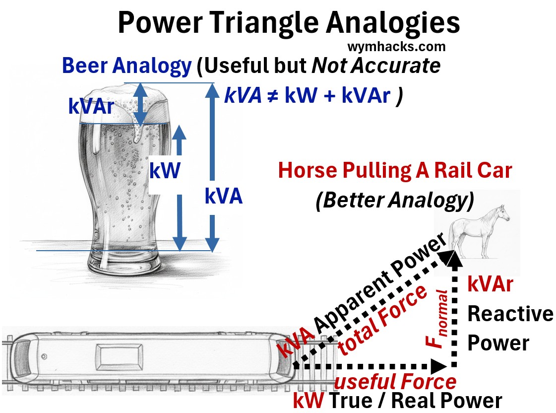
The Beer Glass Analogy (The Flawed Comparison)
You may have seen the “Beer Analogy” used to explain power factor.
In this visualization,
- the liquid beer is the Active Power (the part you want),
- the foam is the Reactive Power (the part you don’t want),
- and the glass is the Apparent Power (the total capacity).
This might help for general understanding but it fails the math.
In a beer glass, the foam and liquid add up linearly (Liquid + Foam = Glass).
But as our derivations show, power adds vectorially.
You cannot simply subtract the “foam” from the “glass” to find the “beer”; you must use the Pythagorean theorem.
Furthermore, foam is just waste, whereas in many AC circuits, Reactive Power is a physical necessity to keep motor magnets energized.
The Horse and Railcar Analogy (The Accurate Physics)
A much more accurate representation is a work and force problem.
Imagine a horse pulling a railcar along a track, but the horse is walking on a path alongside the tracks rather than between the rails.
Active Power (P): This is the horizontal force pulling the railcar forward.
Only the force aligned with the direction of motion performs Work (Work = Force x Distance).
Reactive Power (Q): This is the perpendicular force pulling the car toward the side of the track.
Because the car cannot move sideways, this force performs zero work.
However, it is a physical reality of the setup—the horse cannot pull the car forward without also exerting this sideways tension.
Apparent Power (S): This is the total tension in the rope.
The horse has to exert this full amount of effort, and the rope must be strong enough to handle it, even though not all of that effort results in forward motion.
This analogy perfectly illustrates the Power Factor:
- as the horse walks closer to the track (reducing the angle Φ),
- the “sideways” force (Q) decreases, and
- more of the total tension (S) is converted into forward-moving “Active” power (P).