Alternating Current (AC) Generation
Summary of the Contents (Link to the full posting via the link above or at the bottom of this section)
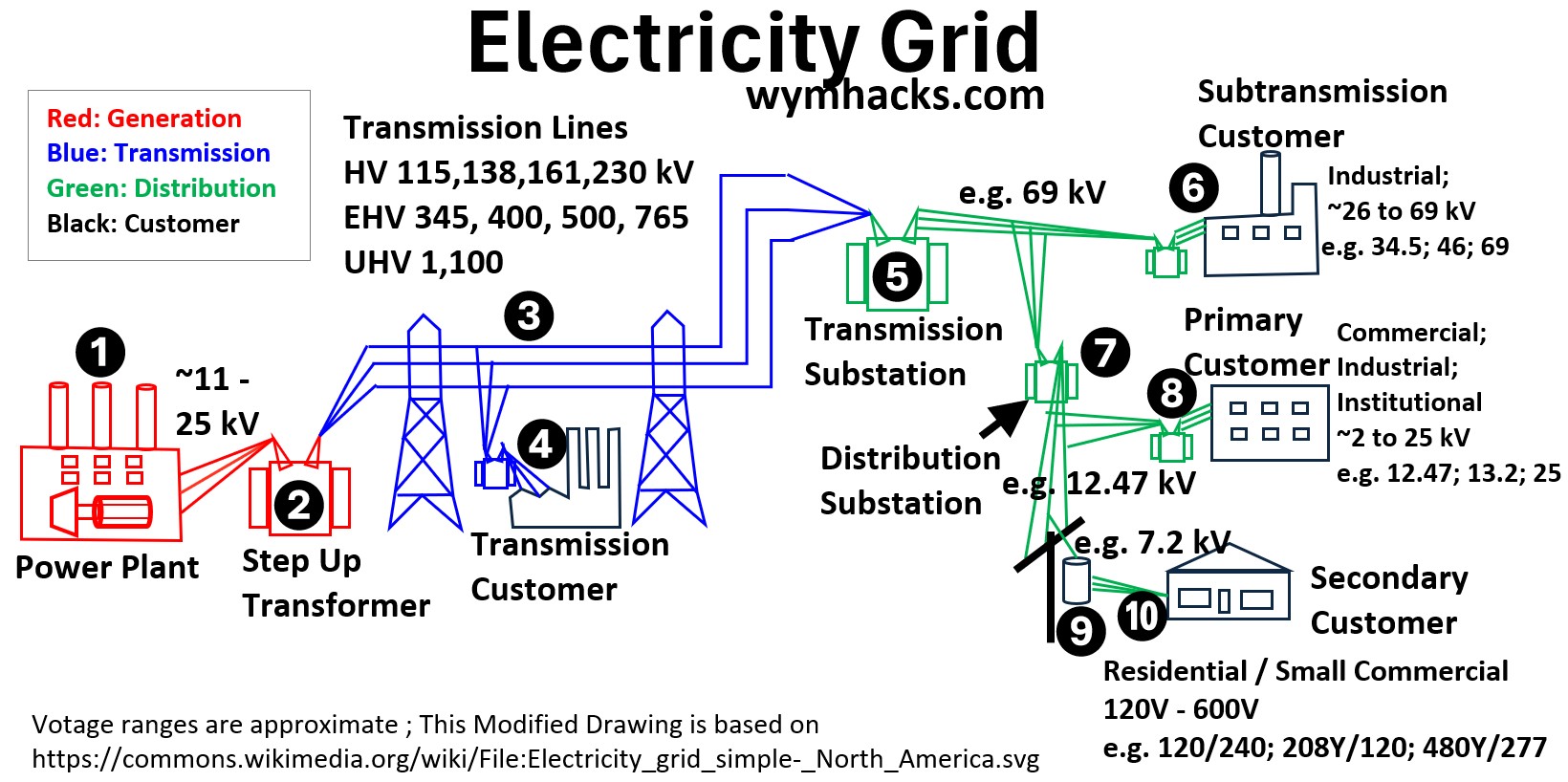
Every time you use that outlet in your house, you are tapping into a massive, synchronized machine that spans hundreds (thousands) of miles.
Picture: Electricity Grid – A Massive Synchronized Machine
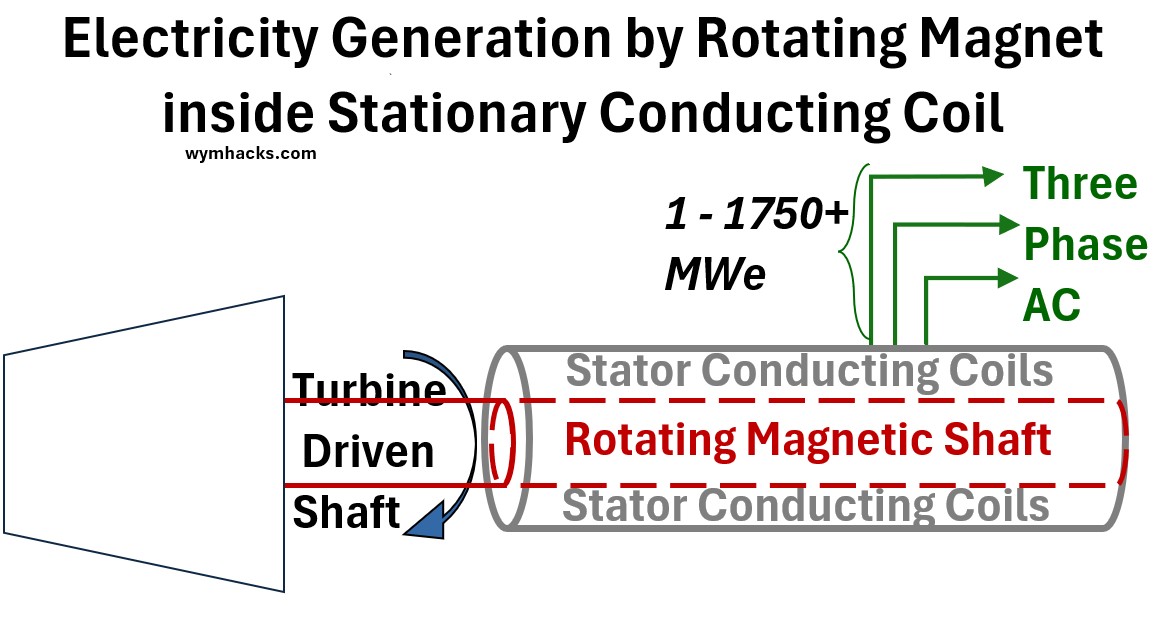
At the heart of this sprawling, interconnected grid lies a surprisingly simple physical “magic trick”: moving a magnet near a wire.
This concept is at the heat of how a power plant electric generator operates (located in the power plant location 1 in the drawing above)
Picture: Electric Power Generator (Rotating Magnetic Shaft in a Stationary Conducting Coil)
Another unique and key piece of technology is the transformer (located at points 2,4,5,6, 7, 8, and 9 in the grid drawing)
Transformers, without which our modern electrical systems could not exist, allow us to increase or decrease voltage as needed.
Transformer designs range from very large three phase devices (as shown in the picture below) to the pole “can” transformers that feed single phase power to your home.
Picture: Three Phase Transformer
This article is a comprehensive guide to how we harvest that simple motion to create Three-Phase Alternating Current (AC), the lifeblood of the modern world.
What we will cover:
- The Physics of Induction: We start with Faraday’s Law to understand why “change” is the most important word in electromagnetism.
- The Geometry of the Wave: We’ll derive the math behind the sine wave and see why a rotating coil naturally produces alternating current.
- The “Flip” in Design: Why real electric generators keep the wires still and spin the magnets instead (it’s a matter of safety and survival).
- The Power of Three: An exploration of why three phases are better than one, and why the “120-degree offset” is the secret to smooth, vibration-free industrial power.
- The Transformer: Why we use AC instead of DC
- Example real world Electric Generator: Faraday’s Law Machine
Please access the full post through this link → Alternating Current (AC) Generation
Wye and Delta Three Phase Circuits
Summary of the Contents (Link to the full posting via the link above or at the bottom of this section)
This article breaks down how three-phase power works.
We start by defining what “phases” actually are and how they interact within sources and loads.
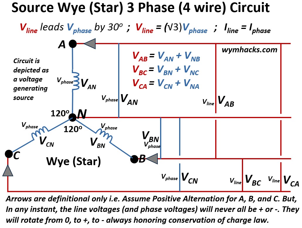
The heart of the discussion focuses on the two essential ways we connect these systems: the Wye (Star) and Delta configurations.
Picture: Wye (Star) 3 Phase (4 wire) Circuit
Picture: Delta 3 Phase Circuit
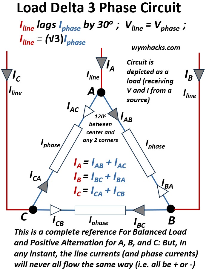
By working through practical examples of both, we will show how current actually flows in a balanced system and how these setups are used across the electrical grid.
Understanding these basics is critical because they are the foundation of nearly every modern power system, affecting everything from energy efficiency to the power factor and impedance of the grid.
Please access the full post through this link → Wye and Delta Three Phase Circuits
Power Plants (Electricity Producing Facilities)
Summary of the Contents (Link to the full posting via the link above or at the bottom of this section)
This post offers a comprehensive journey through the world of power generation and the electricity grid.
We begin by defining the essential components of the Electricity (Power) Grid
before delving into the different Power Plant Types, namely,
- thermal cycle (heat → mechanical motion → electricity generation) or
Picture – Thermal Cycle Power Generation (Steam Boiler/Steam Turbine/Electric Generator)
- direct mechanical cycle (mechanical motion → electricity generation) or
- direct non-mechanical cycle. (Photovoltaics or Batteries/Fuel Cells → electricity generation)
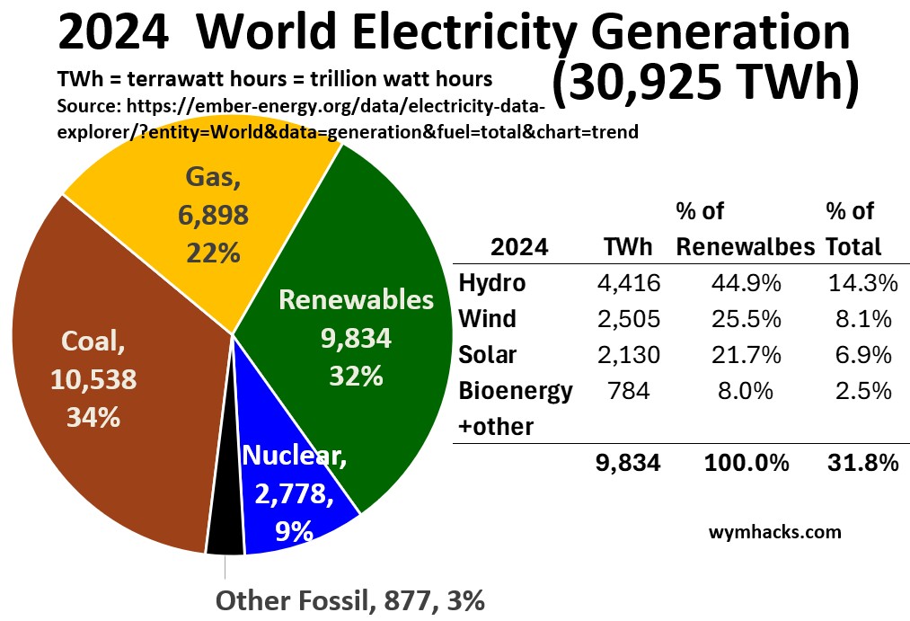
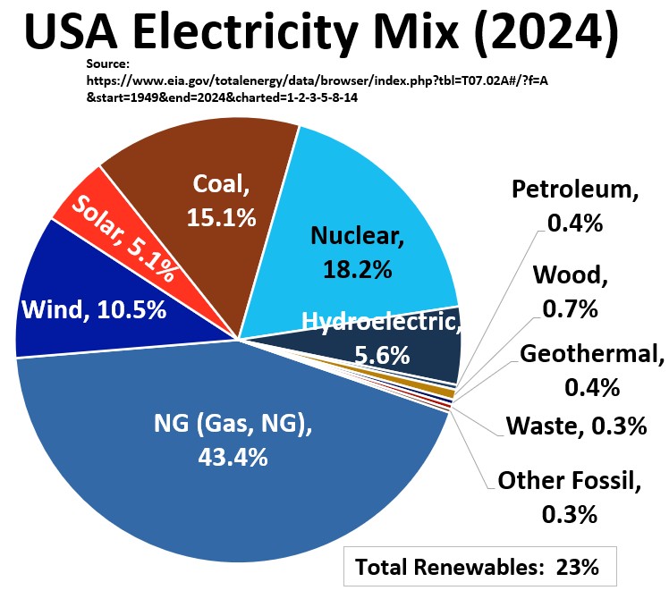
We then show several graphics (like the ones below) and statistics showing Texas (USA), USA, and World power Energy Sources that fuel the power plants.
Picture – 2024 World Electricity Generation
Picture – 2024 USA Electricity Mix
The discussion then moves into the specifics of power plant equipment configurations and technology used in generating electricity, namely,
- Electric power generators
- Steam turbines
- Gas turbines
- Steam boilers
- Heat Recovery Steam Generators (HRSGs)
- Steam from boiler power generation
- Combustion concepts
- Nuclear fission concepts
- Nuclear power plants
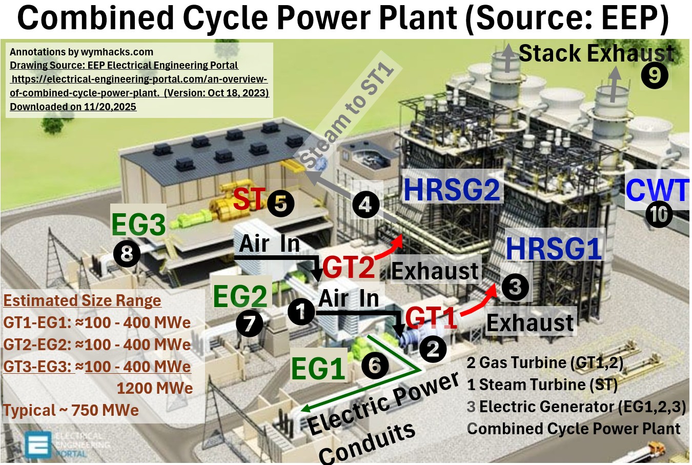
- Combined Cycle Power Plants (CCPP; see the picture below)
- Cogeneration (Combined Heat and Power) plants
- Wind power plants
- Hydroelectric power plants
- Geothermal power plants
Picture: Example 3D Model of Combined Cycle Power Plant
We conclude with sections on energy conversion efficiencies and the efficiency and economics of High Voltage Transmission.
Please access the full post through this link → Power Plants (Electricity Producing Facilities)
Electric Power Line Structures
Summary of the Contents (Link to the full posting via the link above or at the bottom of this section)
Above-ground electrical structures are the primary conduits of the modern power grid, categorized by their voltage capacity and physical architecture.
This article provides a technical overview of the two fundamental tiers of overhead infrastructure: transmission towers and distribution poles.
Transmission Lattice Configurations
High-voltage conductors on lattice towers are typically arranged in vertical, horizontal, or delta (triangular) configurations to maintain phase separation and minimize electromagnetic interference.
Because these lines carry extreme voltages, they often use bundled conductors—two or more cables per phase held apart by spacers—to reduce corona discharge and power loss.
The wires are suspended from the structure by long insulator strings, ensuring the energized lines remain electrically isolated from the grounded steel frame.
Residential Pole Configurations
Distribution lines are generally configured in a vertical or crossarm-horizontal layout.
The “primary” high-voltage wires (typically 7.2kV to 15kV) sit at the top of the pole to maintain maximum ground clearance.
Below these, you will find the neutral wire and the secondary service drops, which are the lower-voltage lines (120V/240V) that connect directly to homes.
Unlike transmission lines, these wires are often crowded by third-party attachments for telecommunications, situated in the “communication space” at the bottom of the electrical zone.
Please access the full post through this link → Electric Power Line Structures
From the Grid to Residential Circuits
Summary of the Contents (Link to the full posting via the link above or at the bottom of this section)
This article provides a technical breakdown of the United States electrical infrastructure, tracing the path of energy from massive regional interconnections down to the individual circuits in your home.
The Macro Grid: Three Interconnections
The U.S. power grid is not a single unified entity but is divided into three primary, independent networks.
Because these systems operate on alternating current (AC) and must be perfectly synchronized at 60 Hz, they are mostly separated to prevent a failure in one region from collapsing the others.
Picture: USA Electric Power Grids
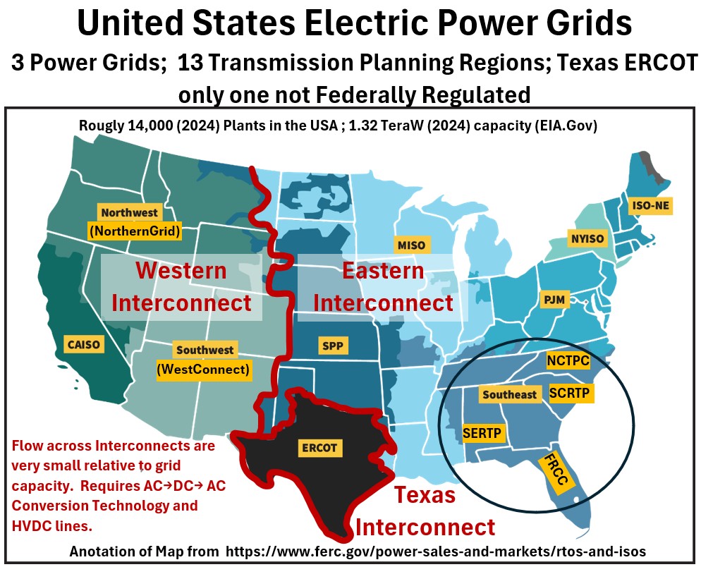
The Eastern Interconnection: The largest network, covering the area from the foot of the Rockies to the Atlantic coast (excluding most of Texas and Quebec).
The Western Interconnection: Encompasses the territory from the Pacific Coast to the edge of the Great Plains.
ERCOT (Electric Reliability Council of Texas): A unique, independent grid covering most of Texas. It is famously decoupled from the other two major interconnections, which allows it to remain largely exempt from federal (FERC) oversight.
The Journey: From Plant to Plug
Electricity follows a specific “step-up and step-down” transformer logic to balance long-distance efficiency with residential safety.
Picture: Electric Grid: From Generator to Home
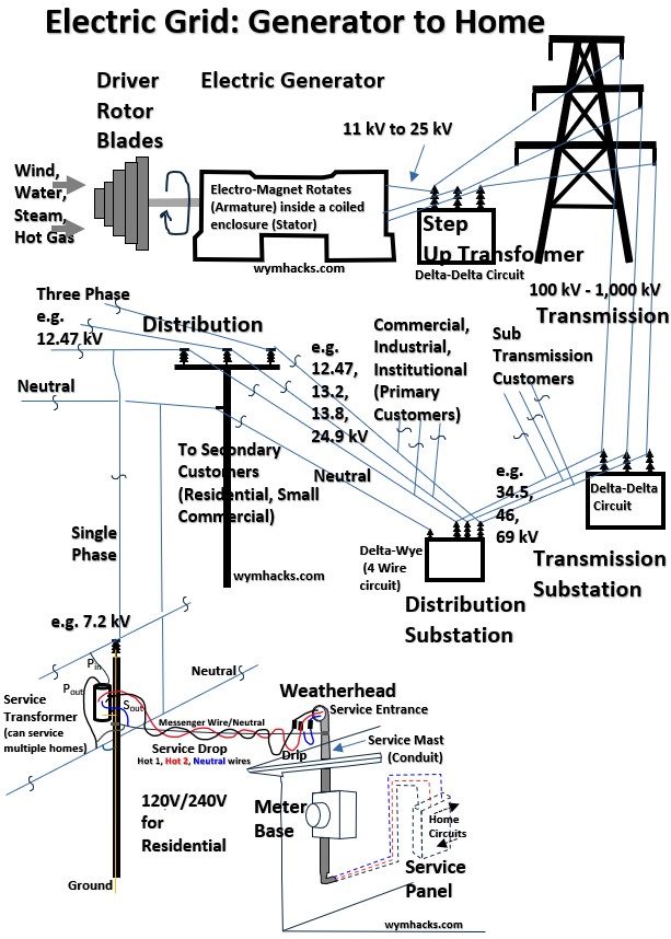
Generation: Power plants (nuclear, gas, hydro, or renewables) produce electricity at relatively low voltages, typically under 30 kV.
Step-Up Substation: To minimize energy loss over long distances, transformers at the plant boost this voltage to “transmission levels” (between 115 kV and 765 kV).
Transmission Lattice: High-voltage towers carry this power across the interconnections.
Distribution Substation: As electricity nears its destination, it enters a substation where it is stepped down to “distribution levels” (typically 7.2 kV to 15 kV).
Neighborhood Poles: The familiar wooden poles carry these distribution lines into your street.
The Service Drop: A final transformer (the “gray bucket” on the pole) steps the power down one last time to the 120V/240V standard required for your home’s breaker panel.
Article Roadmap
Following this overview of the national grid and how a specific grid is connected to your home, the article will detail the internal mechanics of the home:
Home Breaker Panels: The primary distribution point for your residence.
Circuit Examples: Analysis of simple branched circuits versus dedicated subpanel systems.
Technical Appendices: Reference guides for NEC 250 (Grounding/Bonding), wire gauges, and NEMA outlet specifications.