Magnetic Flux
Let’s start with the definition of magnetic flux.
Picture: Magnetic Field B and Magnetic Flux
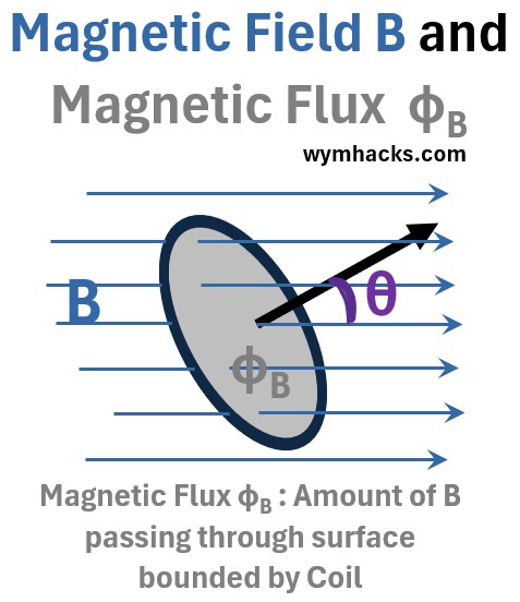
Magnetic flux , ΦB , is the measure of a magnetic field passing through a surface.
ΦB = Magnetic Flux = (B)(Ap) =BAcos(θ) = B̄•Ā ; for Uniform B and Flat Surface where
- ΦB = magnetic Flux (units: (N/C)m2)
- Ap (units: m2) = Perpendicular component of A that the magnetic field passes through.
- B = The magnetic field (units: N/C)
- B̄•Ā = dot product of the magnetic field vector and the area vector.
- θ = angle between area vector and B vector
ΦB = Magnetic Flux =∫BdAcos(θ) =∫sB̄•dĀ for any B for any surface
- For any B through any surface we can restate the equation as the surface integral ∫s of B times infinitesimal areas.
- This is a a general expression for the magnetic flux through any surface
So, what can change magnetic flux? From the equation (and the drawing) we know it is
- A change in the magnitude of B
- A change in the surface area B passes through and
- A change in the angle between B and the surface
Faraday’s Law: Coil in a Magnetic Field
The picture below is a plan view of a magnetic field coming out of the page towards you (represented by the circles with dots…where you can imagine the dots to be the tips of arrows).
We’ll drop a rectangular conducting coil into this field such that its bounded surface is perpendicular to the B field.
Picture: Magnetic Field Lines With Closed Loop Conducting Wire
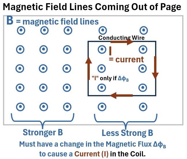
The B field is shown as having various fixed (constant) intensities based on the distance of the points from each other.
As long as the field is constant and the coil is stationary we will not see any current in this coil.
A current “flows” in the wire only if the magnetic flux changes.
So, a current I will start “flowing” in the loop if the magnetic flux changes somehow (ΔΦB > 0):
- e.g. the flux strength decreases or increase
- e.g. the conducting wire boundaries are expanded or contracted
The current I direction is shown going clockwise in the schematic. How do we know that? Read on!
References
Lenz’s Law
Induction and Lenz’s Law (The Negative Sign In Faraday’s Law)
Lets rotate the picture in the previous section so we see a side view of the coil and the magnetic field lines coming up through it (see below).
Now, let’s increase the strength of the magnetic field lines and show these as bigger vectors in the “after the arrow” drawing below (ΦB1 → ΦB2).
Picture: Changing Magnetic Field Lines through a Closed Conducting Wire
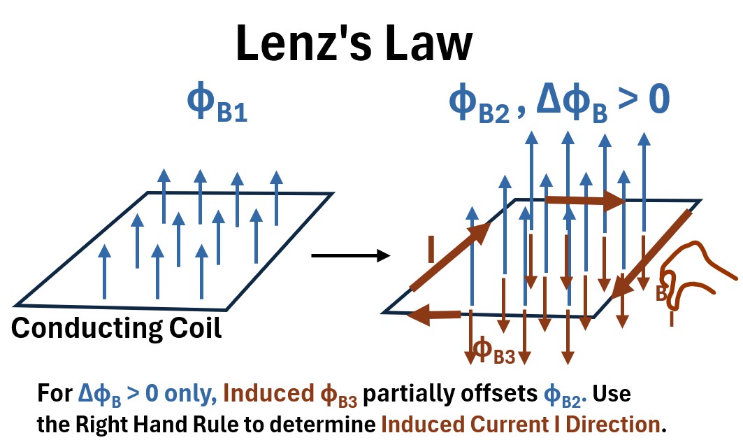
This is what happens:
(1) Change ΦB1 by amount ΔΦB which
(2) induces an Electric Field which
(3) induces a Voltage which
(4) induces Current I which
(5) induces an oppositely directed ΦB3 which
(6) partially offsets ΦB2 .
(7) Based on ΦB3 ‘s direction, use the Right Hand Rule to determine I direction (clockwise in this example).
Lenz’s Law states that the direction of an induced current is such that it creates a magnetic field that opposes the change in magnetic flux that created it.
- This is conservation of energy in action.
- It ensures that to induce a current, you must do mechanical work against a resulting opposing force.
- If the induced current did not oppose the change, it would create a self-perpetuating loop of increasing current and energy from nothing.
Lenz’s law simply states that nature abhors a change in magnetic flux.
- The induced current will always produce a magnetic field that opposes the change that caused it.
- This opposition is why the induced EMF in Faraday’s law has a negative sign
References
This section is mostly based on this great video by Sal Khan.
Motional EMF: Expandable Coil in a Constant Magnetic Field
In the previous section we established a general expression for the EMF for a moving coil in a stationary magnetic field:
Motional EMF = ∮(v̅ x B̅)⋅dL̄
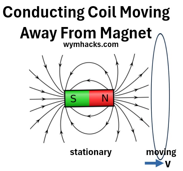
We can simplify this expression (i.e. get rid of the integral) if we assume we now have a conducting coil that is expandable via a moving rod that is connected to it.
It is placed (perpendicularly) into a fixed magnetic field Bo.
Picture: Movable Conducting Coil in a Fixed Magnetic Field
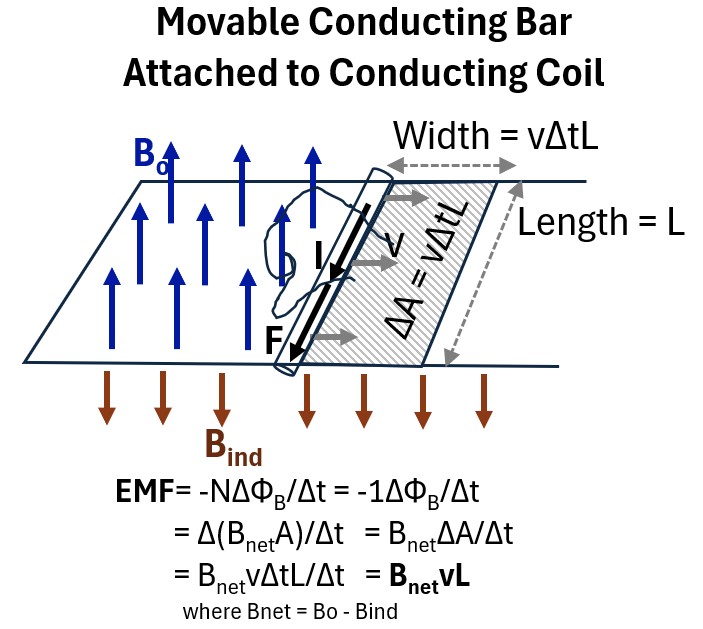
If we move the rod to the right
- for a duration of time Δt
- at a velocity v ,
- it will traverse an area ΔA equal to the product of the length of the bar (L) and the distance traversed (ΔA = vΔtL).
We are dealing with finite distances here so let’s use the average form of Faraday’s Law:
Δt
We also have an expression for magnetic flux:
ΦB = Magnetic Flux = (B)(Ap) =BAcos(θ) = B̄•Ā ; for Uniform B and Flat Surface where
Substitute for ΦB in the EMF expression to get:
Δt = Δt
because
- cos(θ) = cos(0) = 1 and
- B is constant and
- N = 1 (just one coil)
Substitute for ΔA (with vΔtL)
Δt = Δt =
So
Notice that the current that is generated (I) by the moving rod will have a clockwise direction because:
- Lenz’s Law tells us that a counter acting magnetic field will be induced .
- Use the right hand rule on (fingers pointing down) to determine that the current will go in a clockwise direction.
- In the Feynman Lectures (ch.17),for a similar example, is considered to be negligible for a weak current I.
- For completeness we can assume this is a value and we’ll just call it B.
So, in summary, looking at the drawing above, if we move the rod to the right at a velocity v,
- A motional EMF is produced (work or energy per unit charge) = BvL = (Force*Distance)/Charge
- Where B is a composite of the original magnetic field and any induced magnetic field (which is often assumed to be negligible in text book examples).
- So, a Force F is exerted on the electrons in the rod and pushes or moves the electrons (creating current I).
See this great video by Sal Khan: Emf induced in rod traveling through magnetic field
Ok, what about the scenario of a moving magnetic field and a stationary conducting coil?
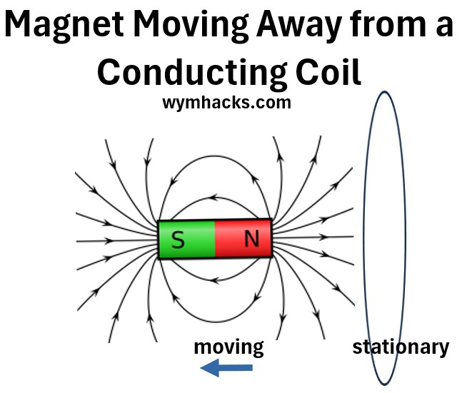
Transformer EMF: Moving Magnetic Field and a Stationary Conducting Coil
In the last section we moved a coil over a stationary magnetic field and found that it is the v̅ x B̅ component of the Lorentz force that creates the EMF that causes the current to flow.
We want to imagine now that we are subjecting a stationary conducting coil to an changing magnetic field.
Picture: Moving Magnetic Field and Stationary Conducting Coil
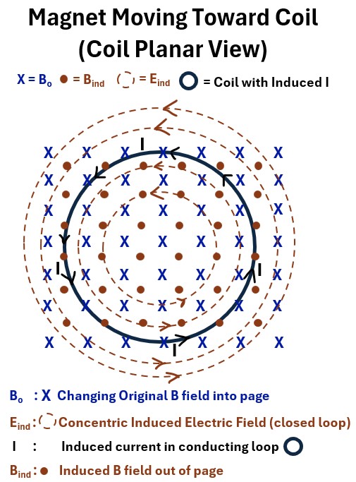
Let’s flip the picture so we have a plan view of the coil (looking down on it from above).
This is the view you see below where
- the solid black circle is the conducting coil and
- X represents the magnetic field going into the page (symbolized as the fletching, the back end, of an arrow).
Picture: Planar View: Changing Magnetic Filed with Fixed Conducting Coil
As , the original or external magnetic field, changes, a current I will begin to “flow” in the coil.
What is the responsible force that makes this happen? Let’s start with our EMF general equation:
EMF=∮(E̅ + v̅ x B̅)⋅dL̄ ; EMF Expression Using the Lorentz Force Components
There are no moving electrons to begin with in this example, so the v̅ x B̅ term is zero!
EMF= ∮Ē•dL̄ ; Transformer
So it’s an Electric field E that forces the electrons around the coil.
- But, very importantly, this E field is NOT an electrostatic field (which is a conservative field)
- E is a very unique , looping, non-conservative Electric field that is able to push the electrons around as current.
More on this E field later , but now lets go through the sequence of events that occur after this E field is created (use the picture above as you read).
- A non conservative , looping, electric field is induced.
- forms concentric closed loop circles that move counterclockwise.
- induces a magnetic field B
- We know B will be opposite according to Lenz’s Law.
- This is represented as the brown dots in the drawing above indicating the induced B field is coming out of the page.
- We can then use the right hand rule (Right hand thumb towards I and curled fingers towards B) to determine the direction of I which will be counter-clockwise.
Let’s come back to the .
is not the same as the electrostatic E field,
So, in a changing magnetic field and a stationary conducting coil, an induced electric field is created and applies the force to move the current.
But is distinctly different than the electrostatic field .
- makes loops (like B fields); has no explicit charge source; not static and always changing
- is created by stationary static charges ; i.e. it starts and stops on a charge and is static
field lines extend radially outward or inward. These fields are conservative, which means the work done by the field on a charged particle moving in a closed loop is always zero.
- So we can say the closed loop line integral on the circuit (i.e. work done) is zero i.e. W/q = ∮Ē•dL̄ = 0
- This is because the force exerted by the field is independent of the path taken and
- only depends on the starting and ending points.
- This property allows us to define an electric potential, where the work done is simply the change in potential energy between two points.
, generated by a changing magnetic field, are non-conservative.
- The work done by on a charged particle moving in a closed loop is not zero.
- There will therefore be no well defined electric potential.
The EMF term, then, is W/q = ∮Ē•dL̄
So we can write Faraday’s Law as follows:
∮Ē•dL̄ = −Nd/dt ; Transformer EMF ; Faraday’s Law of Electromagnetic Induction (line integral form relating E to B)
This equation describes the phenomenon known as Transformer EMF (or non-motional ), where the electric field is induced by a time-varying magnetic field.
- Name: It has different names
- The Maxwell-Faraday Equation (Integral Form) – One of the four Maxwell Equations.
- Faraday’s Law of Induction – Most common and general name
- Physical Meaning: The line integral of the induced electric field () around a stationary closed loop is equal to the negative rate of change of the magnetic flux () through the surface bounded by that loop.
- Requirement: The loop of integration (dL̄) must be stationary (fixed in space).
E is the electric field vector. It is an induced non conservative field (its not an electrostatic field).
- dL̄ is the infinitesimal vector of a path element along a closed loop.
- The direction of this vector is tangent to the path.
- ∮ is a closed line integral. It means you are summing up the dot product of Ē and dL̄ along an entire closed loop.
- The result of this integral is the electromotive force (EMF), which is the work done per unit charge in moving a charge around the closed loop.
- For induced electric fields, this value is non-zero, indicating that the field is non-conservative.
N: # of coils
- is the magnetic flux, which is a measure of the total number of magnetic field lines passing through a given surface
- d/dt = Is the rate of change of magnetic flux with time
- −: The negative sign represents Lenz’s Law.
- It indicates that the direction of the induced electric field (and thus the induced current) will be such that it creates a magnetic field that opposes the change in the original magnetic flux.
- This is a fundamental statement of energy conservation in electromagnetism.
We also know that
ΦB = ∫sB̄•dĀ so let’s substitute this into the expression above to get
∮Ē•dL̄ = −Nd/dt = -Nd/dt∫sB̄•dĀ ; Transformer EMF ; Faraday’s Law of Electromagnetic Induction (line integral form relating E to B)
The Differential Form (The Maxwell-Faraday Equation)
This is the most fundamental and generalized form, fitting in as the final piece.
It extends the concept from a physical loop to any point in space, showing that a time-varying magnetic field (B) creates a circulating electric field (E) at a fundamental level, even in a vacuum.
It is one of the four Maxwell’s Equations and is mathematically derived from the integral form using the Divergence Theorem and Stokes’ Theorem.
Please see how this is derived in my blog post: Maxwell Equations: From Integral to Differential Forms
∇×Ē=-∂B̄/∂t ; Faraday Equation (Differential Form)
This equation shows how fields themselves interact dynamically.