Menu (linked Index)
Lens Equations
Last Update: October 21, 2024
Introduction
In this post we’ll derive the following key lens equations:
- The Lens Magnification Equation
- The Thin Lens Equation
- The Curved Surface Refraction Formula and
- The Lens Makers Formula.
See my article Refractive Geometric Optics where I introduce and describe these equations.
Also, Find more links related to my eye research here: Understand Your Eyes.
I highly recommend you review the following references to help your understanding:
- My Post on Geometry and Trigonometry Rules and Definitions
- U3L3 – How do curved surfaces change the path of light? – Khanacademy
- U3L4 – Lens formula to quickly find where the image will be formed – Khanacademy
- Physics Principles with Applications by Douglas C. Giancoli; 7th Ed; Chapter 23: Light: Geometric Optics
Symmetrical Concave and Convex Lens
In this section we want to get clear on the meaning of the Focal Point F and the Focal Distance f.
Let’s use symmetrical (both sides are the same) convex and concave lenses to define some key measurements. Refer to the picture below as you read on.
Consider incident light rays hitting a lens surface.
According to Snell’s Law the rays will refract inwards or outwards depending on the angles of incidence and the indices of refraction.
I show the normal lines at a and b in the lens pictures below showing how light bends towards or away from the “normal”.
If we assume thin lens (thickness is small relative to the Radius of Curvature), then we can ignore the actual refraction at a and b and just consider a composite refraction occurring at the centerline of the lenses.
Picture_Biconvex and Biconcave Lenses and Focal Point Definition
![]()
The Optical Center (O in the drawings above) of a lens is the point where incoming light rays pass through without being refracted (i.e. straight line through).
- In a symmetrical lens the optical center is located at the geometric center of the lens.
- The Principal Axis is the horizontal line passing through the Optical Center.
- In an asymmetrical lens the optical center may not be at the geometric center.
The Focal Point F of a lens is the point where parallel (to the Principal Axis) light rays “converge” after passing through the lens.
- For Converging Lenses (Convex Lenses), parallel light rays entering the lens will converge (bend inwards) to a single Focal Point.
- For Diverging Lenses (also known as Concave Lenses), parallel light rays entering the lens will diverge (bend outwards).
- The Focal Point is traced back from these diverging rays. We say here that virtual rays traced back from the diverging rays, converge at the Focal Point.
- The Focal Distance f is the distance from F to the Optical Center.
- For symmetrical lenses , F and f are located on both sides, equidistant from the the Optical Center.
Ok, we now know what the Focal Point F and Focal Distance f are.
We want to use Lens Diagrams and a little geometry/trigonometry to derive our equations, so let’s review Ray Diagrams next.
Using Ray Diagrams to Determine the Lens Equations
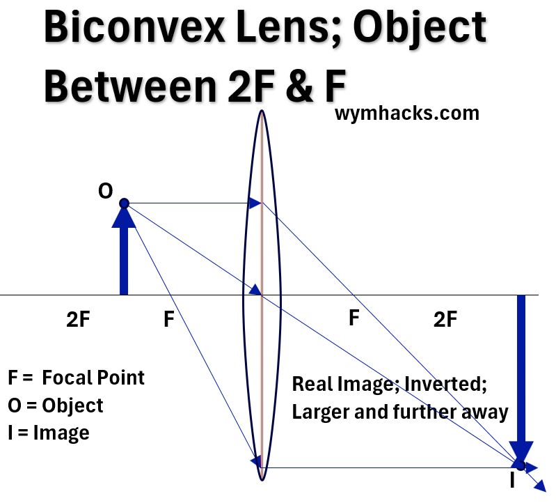
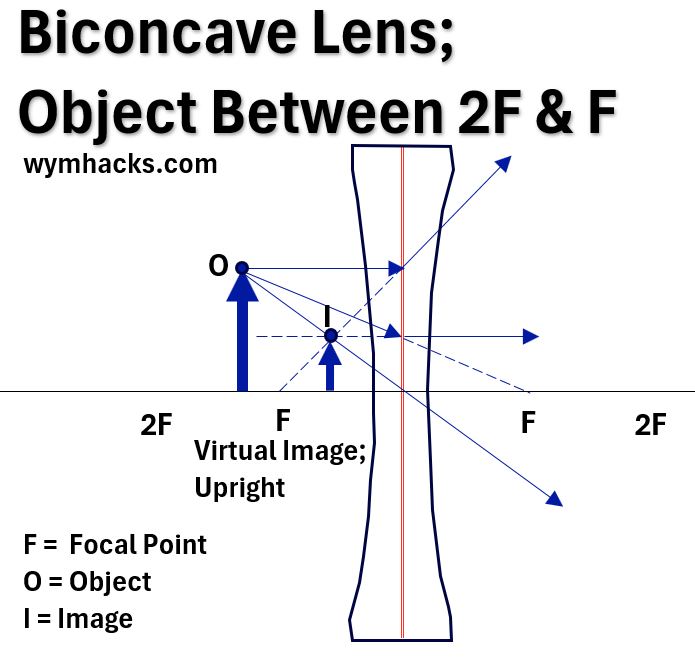
You can go to my Lens Ray Diagrams post for more details on Ray Diagrams , but in this post, we just need to remember the three ray drawing rules for convex and concave lens:
Parallel Ray Rule
- Converging Lens: Any incident ray traveling parallel to the principal axis will refract through the lens and travel through the focal point on the opposite side of the lens.
- Diverging Lens: Any incident ray traveling parallel to the principal axis will refract through the lens and travel in line with the focal point (i.e., in a direction such that its extension will pass through the focal point located on the object side of the lens).
Focal Ray Rule
- Converging Lens: Any incident ray traveling through the focal point on the way to the lens will refract through the lens and travel parallel to the principal axis.
- Diverging Lens: Any incident ray traveling towards F on the opposite side will refract through the lens and travel parallel to the principal axis.
Center Ray Rule
- An incident ray that passes through the center of the lens will continue in the same direction that it had when it entered the lens.
Using any two of the three rules above allows us to locate the Image Point from an Object Point.
In deriving the Lens Equations, we’ll use the Ray Diagrams shown below. I’ve drawn the parallel ray, the focal ray, and the center ray on each one.
Picture_Convex Lens Ray Diagram_Object Between F and 2F
Picture_Concave Lens Ray Diagram_Object Between F and 2F
We can now use basic geometry and trigonometry to come up with some general equations that apply to lenses.
Lens Magnification Equation
We’ll derive the Lens Magnification Equation using a Ray Diagram for a convex lens as described above.
Picture_Convex Lens Ray Diagram for Magnification Equation
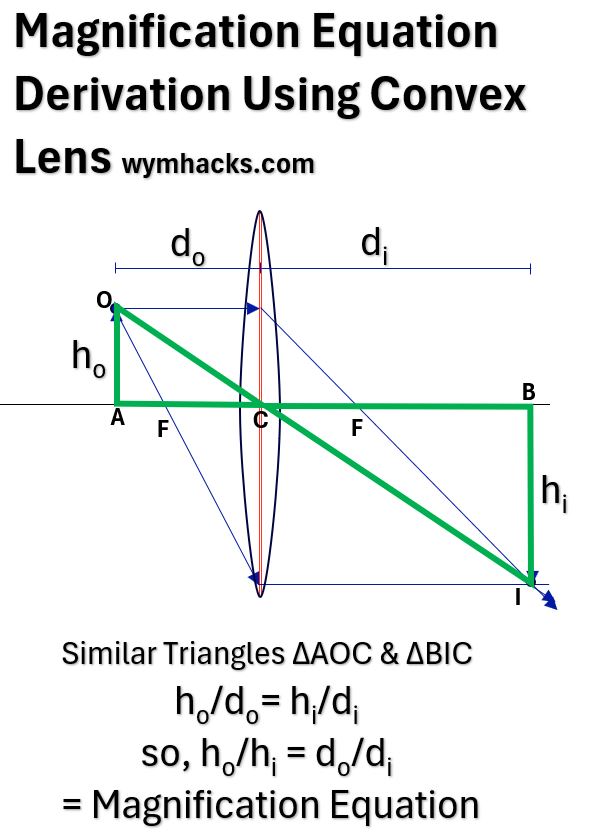
We can use the geometry of similar triangles to determine the Magnification Equation which relates heights (h) of the Object and Image with their distances (d) to the optical center C.
In the drawing above we have Similar Triangles ∆AOC & ∆BIC
so,
- ho/do= hi/di, therefore,
- ho/hi = do/di
We want to have this apply to all lenses (convex and concave) so we want to generalize it with a sign convention.
We’ll apply a cartesian graph sign convention where the (0,0) = C, the optical center of the lens, and where
- distances on the left side of C or downward in direction are negative(-) and
- distances to the right of C or upward in direction are positive (+).
So 2. becomes ho/-hi = -do/di
and the signs cancel out leaving
The Lens Magnification Equation = ho/hi = do/di
ho = Object Height
hi = Image Height
do = X axis Distance of Object to Center
di = X axis distance of Image to Center
Thin Lens Equation
Using a Convex Lens Ray Diagram to Derive Thin Lens Equation
Picture_Thin Lens Equation Using Convex Lens
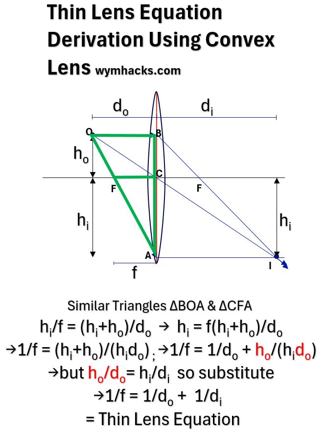
In the Convex Lens Ray Diagram above we have Similar Triangles ∆BOA & ∆CFA, so,
- hi/f = (hi+ho)/do
- hi = f(hi+ho)/do
- 1/f = (hi+ho)/(hido)
- 1/f = 1/do + ho/(hido)
- but ho/do= hi/di , so substitute into 4,
- 1/f = 1/do + 1/di
Equation 6 can be generalized by applying a cartesian sign convention to the distances (Left of Center is negative, Right of Center is positive, Upwards is positive, Downwards is negative).
Applying the sign convention makes do negative. The other values are positive including f which is measured on the right hand side, the side where the actual Focal Point is located.
The general form of the Thin Lens Equation becomes:
Thin Lens Equation: 1/f = 1/di – 1/do
f = focal length, d = Image and Object distance to Optical Center.
Using a Concave Lens Ray Diagram to Derive Thin Lens Equation
The Thin Lens Equation can also be derived using a Concave lens.
Picture_Thin Lens Equation Using Concave Lens
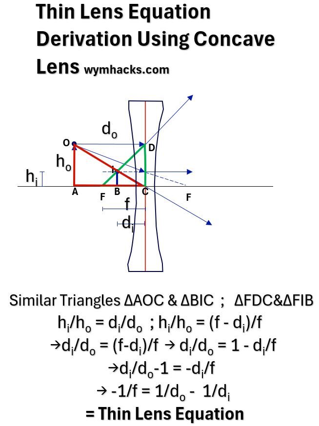
In the Concave Lens Ray Diagram above we have Similar Triangles ∆AOC & ∆BIC and Similar Triangles ∆FDC & ∆FIB so,
- hi/ho = di/do ; hi/ho = (f – di)/f
- di/do = (f-di)/f
- di/do = 1- di/f
- di/do-1 = -di/f
- -1/f = 1/do – 1/di
Equation 5 can be generalized by applying a cartesian sign convention (Left of Center is negative, Right of Center is positive, Upwards is positive, Downwards is negative).
Applying the sign convention makes do and di and f negative. Applying the signs, the general form of the Thin Lens Equation becomes:
Thin Lens Equation: 1/f = 1/di – 1/do
f = focal length, d = Image and Object distance to Optical Center.
Pretty cool. So, this equation can be used to compute one of the variables f, do , and di given the other two.
You can check out the nice videos linked below on derivation and usage of the thin lens equations:
- Thin Lens Equation Derivation – Khanacademy.org
- Solved Example on Lens Formula – Khanacademy.org
- See my article Refractive Geometric Optics
- Michel van Biezen Physics Videos Using Thin Lens Equation
- See the “Physics – Optics: Vision Correction..” video series (1 – 5)
- See the “Physics – Optics: Lenses…” Diverging, Converging, and Combination Lenses series
Curved Surface Refraction Equation Derivation
Now, consider a curved surface in which light is coming through.
Light is coming in via a medium that has refractive index n1 and then gets refracted at entry into the second medium with refractive index n2.
The Object from which the light rays are coming hit the surface as shown in the picture below.
In this picture, the spherical curved surface is a curved red line (which if extended out would make up the circle shown).
In this case the distance from the circle surface to the center would be the Radius of Curvature R (the radius of the circle the curve makes).
- We can draw an Object Ray (line OPCI), which goes straight through because it is perpendicular to the surface.
- We can draw an oblique ray OM to the curved surface.
- We know from Snell’s Law that the light will refract towards the normal (MC) and might look like line MI.
- I will be the image point as it’s an intersection of the perpendicular ray and the refracted ray.
- i and r are the incident and refracted angles
- a, b, and c are angles formed by the triangles shown in the drawing.
Picture_Curved Surface Refraction Drawing
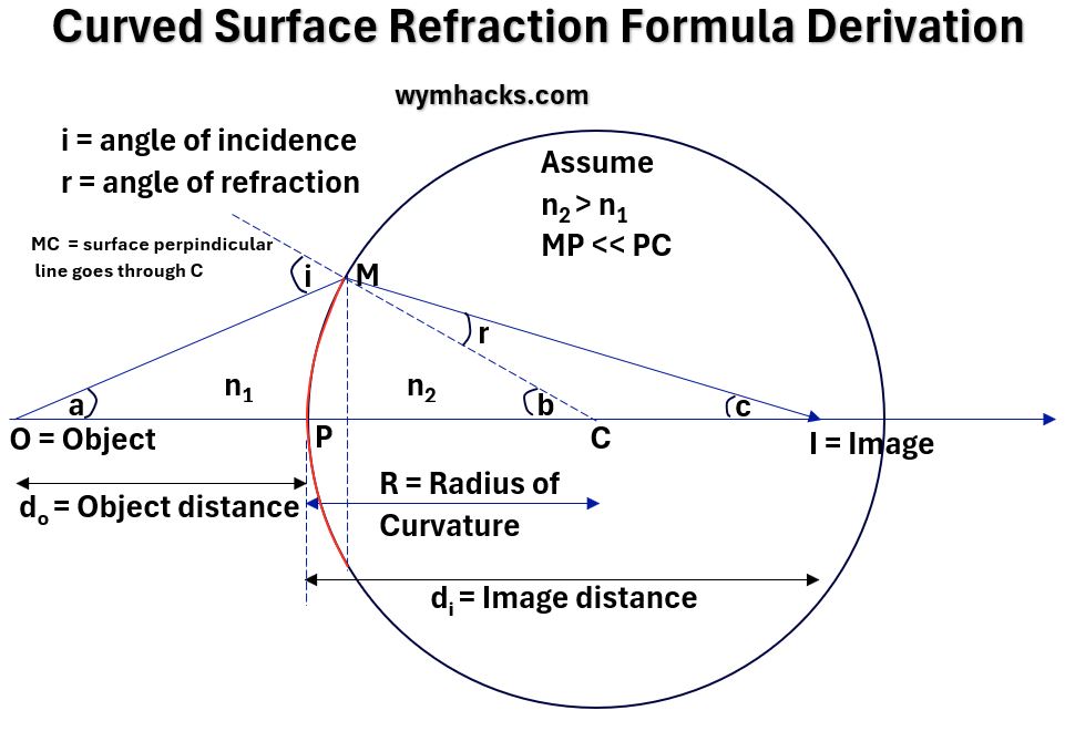
- From Snell’s Law: n1sin i = n2 sin r
- Assume MP is very small compared to PC (which is equal to R)
- so angles i, r, a, b, c become very small and the Small Angle Approximation is assumed.
- So, sin θ = θ and tan θ = θ
- Snell’s Law becomes: n1 i = n2 r
- By Exterior Angle Rule, i = a + b & b = r + c
- Substitute: n1 (a+b) = n2 (b-c)
- tan a = MP/OP = MP/do = a
tan b = MP/PC = MP/R = b
tan c = MP/PI = MP/di = c - Substitute: n1 (MP/do+MP/R) = n2 (MP/R-MP/di)
- Make the formula general by applying sign convention (cartesian x/y with P = 0,0). So do becomes – do.
- n1 (MP/-do+MP/R) = n2 (MP/R-MP/di)
- rearrange : n1 (-1/do+1/R) = n2 (1/R-1/di)
- rearrange : -n1/do+n1/R) = n2 /R-n2/di
- rearrange: n2/di-n1/do = (n2 – n1)/R
General Equation for Curved Surface Refraction:
n2/di – n1/do = (n2 – n1)/R
n = indices of refraction of each medium; R = Radius of Curvature; d = Image or Object distance to Optical Center.
Very nice. You can also check out the following derivation video for Curved Surface Refraction:
Lens Maker’s Equation
Picture_Lens Maker’s Formula Drawing
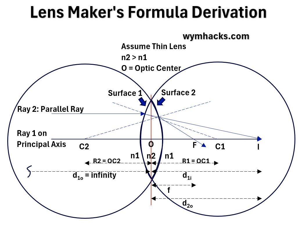
A lens is a “refracting medium bounded by at least on curved surface“.
In the drawing above, we have a lens consisting of two curved spherical surfaces.
Since we said they are spherical, we know that the Radius of Curvature will be the radius of the circle that the curves extend to.
Assume also that the width or thickness of the lens is much smaller than the Radius of Curvature.
This means that the distances between O and the curved surfaces is negligible (say zero).
Consider two parallel (to Principal Axis) rays of light, one on the Principal Axis and the other above the Principal Axis:
- If we just consider Surface 1 alone, the light will refract towards the normal (the dotted line through C1) and land at point I on the axis.
- Including the second Surface 2, moves the line from I to F, the Focal Point. (It refracs away from the normal which is the dotted line through C2).
Assuming the curved surfaces might not be exactly the same, we’ll designate a separate Radius of Curvature for each surface (R1 and R2).
- Recall the Curved Surface Refraction Formula:
n2/di – n1/do = (n2-n1)/R - For Surface 1: n2/d1i – n1/infinity = (n2-n1)/R1
- For Surface 2: n1/f -n2/d2o = (n1-n2)/R2
- But d2o = d1i ,So, n1/f -n2/d1i = (n1-n2)/R2
- Add Surface 1 and 2 equations and re-arrange:
n1/f = (n2-n1)/R1 + (n1-n2)/R2
n1/f = (n2-n1)(1/R1 – 1/R2)
1/f = 1/n1(n2-n1)(1/R1 – 1/R2) - 1/f = (n2/n1-1)(1/R1 – 1/R2)
Lens Maker’s Formula:
1/f = (n2/n1-1)(1/R1 – 1/R2)
f = lens focal length; n = indices of refraction of each medium; R = Radius of Curvature of each surface
This applies to convex or concave thin lenses.
Check out the videos below for derivation of the equation and examples of how the equation can be used.
- Lens Maker’s Formula Derivation – Khanacademy.org
- Solved Example Lens Maker’s Formula – Khanacademy.org
- Michel van Biezen Physics Videos Using Lens Maker’s Equation
- See the “Physics – Optics: Lensmaker’s Equation” series (1 of 5)
Disclaimer: The content of this article is intended for general informational and recreational purposes only and is not a substitute for professional “advice”. We are not responsible for your decisions and actions. Refer to our Disclaimer Page.
