Introduction
The electrical transformer is a passive, static device that serves as the backbone of the vast electrical machine we call “the grid.”
Picture: Transformers in the Grid
Its primary job is simple but vital: it changes the voltage of electricity.
By increasing or decreasing voltage, it allows power to be moved over vast distances and then safely delivered to your wall outlet.
It is not just a single component but a critical link interspersed throughout the entire power system—from the large three phase transformers at power plants to the small green boxes (on ground) or “cans” (on poles near your house) in your neighborhood.
By operating on the principles of electromagnetic induction, it allows for the efficient transfer of energy between circuits while maintaining a constant frequency (60 Hz in the United States) .
- A transformer changes the Voltage (V) and the Current (I), but the Frequency (f) stays exactly the same.
Because it contains no moving parts and requires no external power source to operate, it remains one of the most reliable and efficient machines in engineering.
Understanding the transformer is essential for analyzing grid stability, especially as residential loads increase.
This post provides a technical breakdown of transformer technology,
- moving from the fundamental governing equations of induction
- to the physical anatomy of the distribution hardware found in residential neighborhoods.
We will examine how these units are classified, how they are sized according to service ratings, and the specific mechanics of how a pole-mounted unit steps down primary distribution voltage for a standard home connection.
Transformers: What do they look like?
A transformer is a stationary electrical device (no moving parts) that transfers energy between two or more circuits through electromagnetic induction.
By energy transfer we typically mean voltage being increased (stepped up) or decreased (stepped down)
It consists of two coils of wire (the primary and secondary windings) wrapped around a common iron core;
- when an alternating current flows through the primary coil,
- it creates a fluctuating magnetic field
- that induces a voltage in the secondary coil.
Let’s look at what these devices might look like.
In a power plant three phase step up transformer, like the one in the drawing below, there will be three sets of primary and secondary windings that are wrapped around a central core.
Picture: Typical Look of a Step Up or Step Down Three Phase Transformer
![]()
Or we could have much simpler designs like a pad mounted three phase step down transformer (providing power to a commercial or residential building)
or a typical single phase step down transformer that feeds you house (see the picture below)
Picture: Typical Design of a Single Phase (Can shaped) Step Down Transformer that Feeds your house
![]()
The transformer that typically provides single phase to your home has the typical cylindrical or “can” shape you see hanging from utility poles in your neighborhood.
Inside this “can” there will be a primary and a secondary coil wrapped around an iron core.
Regardless of the specific design, without the transformer, electrical transmission and distribution systems (that get electricity to your house) would not work.
They provide Voltage Conversion
- by “stepping up” voltage to extremely high levels for efficient long-distance travel
- By increasing voltage, the transformer drastically reduces the current.
- Since heat loss in wires is caused by current, this allows us to move power over very long distances very little energy wasted.
- or by “stepping down” to safe levels (like 120V) for your wall outlets (or other end use customers)
Transformers – working & applications (step up and step down) – Khanacademy
The Power of “Stepping Up”
The most efficient way to move electricity is at super-high voltage and low current.
According to Joule’s Law (P = I2R),
- the energy lost as heat is proportional to the square of the current.
By using a transformer to “step up” the voltage, we can drop the current significantly, which drastically reduces the amount of energy wasted as heat in the transmission lines.
Why Only AC?
Transformers rely on electromagnetic induction, which requires a constantly changing magnetic field to work.
Because AC current is always oscillating (graphs as a sinusoidal wave over time), it naturally creates this changing field.
Direct Current (DC) stays at a constant level, so it cannot be easily stepped up or down with simple, inexpensive transformers.
The ability of transformers to cheaply and easily transform voltage levels at both ends of the wire is why AC became the global standard for the power grid.
Transformers Across the Grid
To understand why the grid is called the “largest machine ever built,” you have to look at the transformers.
They are the gatekeepers of energy, strategically placed to ensure power can travel hundreds of miles without evaporating into thin air as heat.
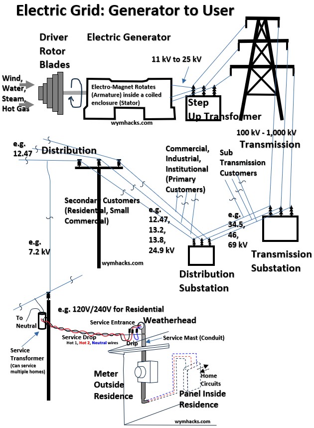
Here is how electricity travels from the generator to your toaster, changing voltage at every stop.
Picture: Electricity Grid
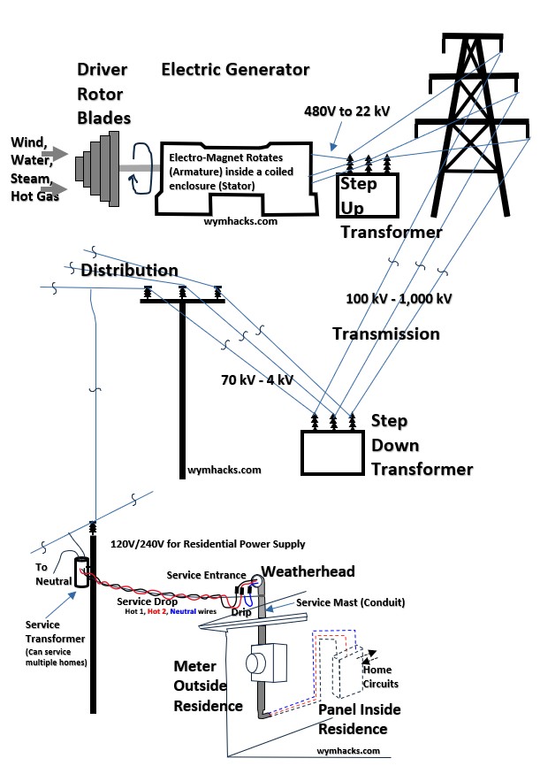
The Power Plant: The Great Step-Up [1 in the drawing]
Electricity is typically generated at relatively low voltages (around 11kV to 25kV).
However, pushing that much current over long distances through copper wires creates massive heat loss (P = I2R).
- The Location: Just outside the generating station.
- The Job: A massive Step-up Transformer boosts the voltage to “extra-high” levels—anywhere from 115kV to 765kV (or higher).
- The Result: By “stepping up” the voltage, we “step down” the current. Lower current means less heat, allowing us to ship power across states efficiently.
Transmission Lines & Industrial Customers [4 in the drawing]
As these high-voltage lines crisscross the country, they occasionally “tap” off to serve Large Industrial Customers (like steel mills or massive factories).
These facilities have their own dedicated substations to bring that high voltage down to a level their heavy machinery can handle.
Transitioning to Sub-transmission [5 and 6 in the drawing]
As we get closer to cities and towns, we can’t safely run 500kV lines over residential streets.
- The Location: Transmission Substations.
- The Job: These transformers step the voltage down to Sub-transmission levels (roughly 34kV to 69kV).
- The Customers: Some “Sub-transmission” customers, like large hospitals or universities, take power at this level.
Distribution Substations: Entering the Neighborhood [7 and 8 in the drawing]
Now we enter the local stage.
- The Location: Those fenced-in areas you see near shopping centers or residential neighborhoods.
- The Job: The Distribution Transformer steps the voltage down again, usually to a “Primary Distribution” level (perhaps 2kV and 25kV).
- The Route: This power travels along the wood or concrete poles you see lining the streets.
Pole-Mounted / Pad-Mounted: The Final Step [9 and 10 in the drawing]
The power on the street poles is still far too high (e.g., 7,200V) to enter your home.
- The Location: The gray “trash can” looking cylinders on poles (Pole-mounted) or the green metal boxes on the ground (Pad-mounted).
- The Job: This is the final Step-down Transformer. It takes that neighborhood voltage and drops it to the standard 120V/240V used in your house.
- The Delivery: This is the “Secondary” service that finally enters your electrical panel.
Summary
Here’s another simplified view of a power grid.
Picture: Power Grid
Stage: Power Plant
- Transformer Type: Step-Up
- Main Goal: Efficiency for long distance
- Typical Voltage: 20kV → 500kV
Stage: Transmission Substation
- Transformer Type: Step-Down
- Main Goal: Safety & Regional routing
- Typical Voltage: 500kV → 69kV
Stage: Distribution Substation
- Transformer Type: Step-Down
- Main Goal: Local neighborhood routing
- Typical Voltage: 69kV → 13kV
Stage: Service Point
- Transformer Type: Step-Down
- Main Goal: Residential and Commercial use
- Typical Voltage: 13kV → 120V/240V
Electrical Transformer Governing Equations
Several equations describing electrical transformer operation come out of Faraday’s Law of Induction.
We’ll describe the main ones in this section.
An electrical transformer transfers energy between circuits through a shared magnetic field.
- It is a passive device because it does not generate its own energy or provide power gain;
- instead, it simply transfers and modifies existing electrical energy from one circuit to another.
- It is also classified as a static device because it contains no moving or rotating parts, relying entirely on electromagnetic induction within a fixed structure to operate.
- Because there is no mechanical friction involved,
- transformers are exceptionally efficient (96 – 99%) and
- require very little maintenance compared to dynamic electrical machines.
The picture below is an idealized model of a simple transformer.
Picture: Transformer Concept
![]()
It consists of a primary coil (the input) and a secondary coil (the output) wound around a common ferromagnetic core.
- “ferromagnetic” refers to a material (like iron, nickel, or cobalt) that possesses a high magnetic permeability, allowing it to become strongly magnetized and act as a highly efficient “bridge” or conduit for magnetic flux.
So, this core acts as a high-efficiency magnetic conduit, ensuring that energy “jumps” from one coil to the other with minimal loss.
An AC source applies a voltage (Vp ) to the primary coil (which has Np turns), driving an AC (alternating current).
This current generates a continuously varying magnetic flux (Φ) within the ferromagnetic core.
Flux Linkage
The core acts as a “highway” for the magnetic field, channeling the flux from the primary leg to the secondary leg.
The total amount of magnetic flux that passes through, or “links,” every turn of a coil is called the Flux Linkage.
Since both coils share the core, they experience the same rate of change of flux (dΦ/dt).
Faraday’s Law
Electric transformers operate on the principle of mutual electromagnetic induction, a process where a changing magnetic field in one circuit induces a voltage in a second, electrically isolated circuit.
This operation is fundamentally governed by Faraday’s Law of Induction, which states that
- the induced electromotive force (EMF) in any closed circuit is equal to the negative rate of change of the magnetic flux (Φ) through that circuit.
In a transformer, the alternating current in the primary winding generates a continuously varying magnetic flux (Φ).
This flux is channeled through a high-permeability core to link with the secondary winding, inducing a proportional voltage based on the number of turns in each coil.
For a coil with N turns, the induced voltage (V) is:
t ; Faraday’s Law
See my post: Faraday’s Law and Lenz’s Law
Using Faraday’s law and treating the transformer as an “ideal” device we can establish the baseline physics.
Deriving The Transformer Turns Equation
For the primary and secondary coils, the relationships are:
(2) Vp = –NpdΦ/dt; Faraday’s Law Ideal Transformer Primary Coil
(3) Vs = –NsdΦ/dt; Faraday’s Law Ideal Transformer Secondary Coil
Primary Voltage (Vp)
An alternating voltage applied to the primary coil creates a time-varying magnetic flux (Φ) in the core.
The equation shows that the primary voltage is equal to the rate of change of this flux multiplied by the number of turns.
Secondary Voltage (Vs)
This same changing flux travels through the core and “links” with the secondary coil.
This induces an electromotive force (EMF) in the secondary coil, proportional to its number of turns (Ns).
The Negative Sign
This represents Lenz’s Law.
It states that the induced voltage will always have a polarity that opposes the change in magnetic flux that created it—a fundamental requirement for the conservation of energy.
The Common Term (dΦ/dt)
In an ideal scenario, we assume the core has infinite permeability and zero leakage, meaning the rate of change of flux is identical for both coils.
Key Idealizations (see Appendix 1) : By using these two equations as the sole description of the device, you are making three specific assumptions
- Zero Resistance: i.e. the copper wires have no resistance, so there is no internal voltage drop (IR).
- Perfect Coupling: i.e. every line of magnetic flux stays inside the core and reaches the other side (no leakage flux).
- No Core Losses: i.e. the iron core does not heat up from magnetic friction (hysteresis) or swirling internal currents (eddy currents).
Transformer Turns Equation
We can can equate the common terms in equations (2) and (3) to get
(4) Vs/Vp=Ns/Np
The is the Transformer Equation which states that the ratio of the secondary to primary voltages in a transformer equals the ratio of the number of loops in their coils.
The secondary voltage of a transformer can be less than, greater than, or equal to the primary voltage, depending on the ratio of the number of loops in their coils.
- A step-up transformer is one that increases voltage, whereas
- a step-down transformer decreases voltage.
Picture – Transformer Types
Transformer Power, Voltage, Current and Turns Relationships
Assuming resistance is negligible, the electrical power output of a transformer equals its input.
This is nearly true in practice—transformer efficiency often exceeds 99%.
Equating the power input and output, we get
(5) Pp =IpVp= IsVs= Ps ; Power Relationship (Ideal Transformer)
Equation (5) states that the Input Power in the primary coil is exactly equal to the Output Power in the secondary coil.
- In an ideal world, the transformer is 100% efficient.
- It reminds us that a transformer cannot “create” energy; it can only trade voltage for current.
- If you step up the voltage, the current must drop to keep the total power the same.
(6) Vs/Vp=Ip/Is ; Voltage-Current Relationship (Ideal Transformer)
As we noted, voltage and current are inversely proportional.
- If the secondary voltage is twice as high as the primary voltage,
- the secondary current will be half the primary current.
- This is why high-voltage transmission lines use very low current—it allows them to move the same amount of power while losing very little heat to the resistance of the wires.
Substituting equation (4) for Vs/Vp we get
(7) Ns/Np =Ip/Is ; Current-Turn Relationship (Ideal Transformer)
By substituting the voltage-turn ratio into the equation, we link the physical construction of the transformer (the number of wire loops) directly to the current.
- This tells us that the coil with more turns will always have less current.
- Conversely, the coil with fewer turns will carry more current.
- This is why the “low-voltage” side of a transformer usually has much thicker wires—it has to handle the higher current safely.
Because this mechanism depends entirely on a continuously changing magnetic field (dΦ/dt ≠ 0), transformers are strictly AC devices.
- If connected to a steady Direct Current (DC) supply,
- the flux remains constant,
- the derivative becomes zero, and
- no voltage is induced in the secondary coil.
Self-Inductance: The Coil’s “Inertia”
When we look at a single coil (an inductor), we define its self-inductance (L) based on how much flux linkage () it creates per unit of current (i):
(8) L = /i
wuz link (eqn 4 in 7/11)
or
= Li/N
- where Nis described as the “flux linkage”.
- A coil’s inductance ,L , is an electrical inertia, resisting changes in the current through it.
- Flux linkage () is a measure of the magnetic “inertia” stored in the inductor’s magnetic field.
So Self Inductance represents the coil’s tendency to resist changes in current.
Starting with Faraday’s law, we can substitute for Φ= Li/N to get
(10) V = -NdΦ/dt = -Nd(Li/N)/dt = -Ldi/dt
These equations shows why transformers only work with AC (alternating current); if the current doesn’t change, the flux doesn’t move (dΦ/dt = 0 ), and no voltage is induced.
Enhancing the Field: The Role of the Core
To make a transformer efficient, we need a strong magnetic field.
The following Equations describe how we build a better “magnet”.
The Solenoid:
(11) B = μ0Ni/ds ; Magnetic Field Magnitude in a Solenoid
The field strength increases with more turns and more current. (wuz link)
The Core:
By adding a ferromagnetic core, we introduce relative permeability (r).
(12) L = r0
Where (wuz link)
- L = Self Inductance
- N = number of loops in the coil
- The total permeability of any material = product of the permeability of free space and the relative permeability of that specific material
- =
- μ0 = a constant; the Permeability of Free Space (for air or vacuum)
- μr = a constant; the Permeability of the core (ferromagnetic material).
- For air/vacuum: ≈1
- For ferromagnetic cores: can be very large (e.g., 5,000 for soft iron).
- A = bounded area of each loop
- = length of the solenoid coil
Practically, the core acts like a “highway” for magnetic flux, channeling it from the primary coil to the secondary coil so almost nothing is lost to the air.
Mutual Induction: The “Bridge”
The defining characteristic of a transformer is Mutual Inductance (M).
This is the measure of how effectively the magnetic field from the primary coil (L_1) “links” to the secondary coil (L_2).
The voltage (EMF) induced in the secondary (s) coil is driven by the change in current in the primary (p).
(13) Vs = EMFs = – Mdip/dt ; Mutual Inductance Equation
(14) M = k√(LL) ; Mutual Inductance (M) between two coils
This defines the Mutual Inductance (M) between two coils based on their
- individual self-inductances (L and L) and
- how well they are magnetically linked.
The Coupling Coefficient (k): This is a value between 0 and 1 that represents the efficiency of the magnetic connection.
- If k=1, the coils are “perfectly coupled” (all magnetic flux from one hits the other);
- if k=0, they are completely isolated.
The term √(LL) represents the theoretical maximum mutual inductance possible for those two specific coils.
Practical Meaning: In the real world, M is always less than or equal to this geometric mean because some magnetic flux “leaks” into the surrounding air rather than passing through the second coil
The Real-World Picture: Total Induced EMF
In a working system, the coils are constantly interacting.
where
- M= Mutual Inductance of coil 1 with respect to coil 2
- M= Mutual Inductance of coil 2 with respect to coil 1
- It turns out that M will always equal M so we can express it as M.
- the sign convention for the M terms will depend on the the construction of the coils (the side of the coil in which the winding starts and the direction of the coil winding)
- LL= Self Inductance of coil 1 and 2 respectively.
EMF = -Ldi/dt – Mdi/dt = -Ldi/dt – Mdi/dt
What this means practically:
- The first term (-Ldi/dt) is the coil resisting the change in its own current.
- The second term (- Mdi/dt) is the “feedback” or load effect.
This interaction is why, when you plug a heavy appliance into the secondary side, the primary side “feels” the load and draws more current from the source to compensate.
Transformer Classifications
Picture: Some Transformer Types
![]()
Transformer Classifications
The table below is not 100% complete, but it shows some of the typical ways that transformers can be classified.
Table: Transformer Classifications
![]()
For our purposes , the key distinguishing feature of transformers is their voltage increasing or decreasing functionality which we’ve already covered.
But there are other features worth mentioning.
Number of Phases
Single-Phase Transformers
Single-phase transformers are designed for light-duty applications, primarily residential and small commercial loads.
- They utilize a single pair of coils or winding (primary and secondary) to step down voltage from the distribution line to the standard 120V and 240V used in homes.
- Because they operate on a single alternating current wave, the power delivery pulsates, which is sufficient for lights and appliances but less efficient for heavy industrial machinery.
- You’ll recognize these most commonly as the “can-type” transformers mounted on utility poles.
Three-Phase Transformers
Three-phase transformers are the backbone of industrial power and the high-voltage grid, consisting of three sets of windings linked together in a single unit.
- By staggering three separate AC signals 120 degrees apart, they provide a continuous, “ripple-free” flow of power that is much more efficient for long-distance transmission and heavy-duty motors.
- This design is more compact and cost-effective than using three separate single-phase units, making it the standard choice for power plants and large-scale distribution substations.
Construction: Core-Type Transformer
![]()
In a core-type design, the windings (the conducting coils) surround the core.
The magnetic circuit is essentially a frame, and the copper coils are wound around the “limbs” of that frame.
Single-Phase Core Type
- Structure: A simple rectangular magnetic core with two vertical limbs.
- Winding: Half of the primary and half of the secondary windings are placed on each limb to minimize “leakage flux.”
- Characteristics: It requires more copper but less iron.
- Because the windings are on the outside, they are easier to cool and insulate, making this design common for high-voltage applications.
Three-Phase Core Type
- Structure: A core with three vertical limbs connected by a top and bottom yoke.
- Winding: Each limb holds the primary and secondary windings for one phase (Phase A, B, and C).
- Characteristics: This is the most common transformer for substations.
- It is lighter and smaller than a three-phase shell type because the magnetic flux of the three phases is interconnected, allowing for a more efficient use of the steel.
Construction: Shell-Type Transformer
![]()
In a shell-type design, the core surrounds the windings. This acts like a “shell” or a protective armor for the coils, providing superior mechanical strength.
Single-Phase Shell Type (The “Pole Can” Standard)
- Structure: A three-legged core (often made of E-shaped and I-shaped laminations). The center limb is twice as wide as the two outer limbs.
- Winding: Both the primary and secondary windings are stacked together on the center limb.
- The Utility Standard: This is the design used for the pole-mounted “can” outside your house. It is chosen for its compact size and its ability to withstand the massive physical forces of a short circuit.
Three-Phase Shell Type
- Structure: Essentially three single-phase shell units stacked together. It typically features five limbs (three for the coils and two “outer” limbs to provide a return path for the magnetic flux).
- Characteristics: These are massive and heavy. They provide independent magnetic paths for each phase, meaning if one phase fails, it is less likely to affect the others. They are typically found in high-capacity generating stations.
Application (their specific job)
When classifying transformers by their specific job on the grid, they are generally divided into three main categories based on where they sit and what they are “measuring.”
Refer to the “Some Transformer Types” picture above.
Power Transformers
Power transformers are the giants of the electrical world, used at the ends of high-voltage transmission lines to step voltage up for long-distance travel or down for regional distribution.
- They are designed to operate at near-constant full load and maximum efficiency.
- Because they handle massive amounts of energy (often exceeding 200 MVA = mega volt amps = unit of power = energy/time),
- they are built with heavy-duty cooling systems, such as large external radiators and fans, to dissipate the intense heat generated by the core and windings.
- (often have tell tale mineral oil storage tanks on top of them)
- MVA refers to the total or apparent power required (we discuss this in more detail in a later section)
Distribution Transformers
Distribution transformers are the “final link” in the chain, stepping down the voltage to a level safe for end-users (240V/120V for homes or 480V for businesses.
- Unlike power transformers, these units are designed for maximum efficiency at lower loads because residential power demand fluctuates throughout the day.
- These are most commonly seen as the pole-mounted “cans” or the green metal “pad-mount” boxes in residential neighborhoods.
Instrument Transformers
Instrument transformers are high-precision devices used to “scale down” dangerous voltages and currents to safe, measurable levels for meters and protective relays.
They ensure that sensitive equipment—and the people reading it—are physically isolated from the high-voltage lines. There are two primary types:
- Current Transformers (CT): These wrap around a high-current conductor to produce a proportional, much lower current (usually 5A) for measurement.
- Potential Transformers (PT): Also known as Voltage Transformers, these are connected in parallel to the line to step down high voltages (like 13.8 kV) to a standard metering voltage (usually 110V or 120V).
Transformer Characteristics by Grid Level
Here are tabulations and listings of transformer characteristics listed by Grid Level.
Picture: Table: Transformer Types and Ratings
![]()
Picture: Table: Transformer Types and Ratings (Full Table)
![]()
You might want to refer to the following to refresh on single phase versus three phase power as well as the different power definitions for AC circuits.
- AC Circuits: I-V Relationships, Impedance, Admittance, and Power
- Wye and Delta Three Phase Circuits
- Electrical Power Equations
Before we list them, here are brief descriptions of what the categories mean.
Grid Level
This identifies the location within the power hierarchy.
- It tells you where the transformer sits on the journey from the spinning turbine to the wall outlet.
Levels: Generation → Transmission → Sub-Transmission → Distribution → End Use.
Style
This defines the functional direction of the voltage.
- Step-Up: Increases voltage (reduces current) for efficient long-distance travel.
- Step-Down: Decreases voltage to levels safe for cities, buildings, and eventually, hair dryers.
Mounting
This describes the physical installation and cooling environment.
- Pad/Base: Large units sitting on concrete, cooled by massive radiators and oil.
- Pole: Smaller “cans” hanging in the air to stay away from people and utilize air cooling.
- Vault: Specialized units designed for underground or basement “bunkers” in cities.
Phase
The electrical configuration of the windings.
- 3-Ph (Three-Phase): The standard for industrial and grid-level power.
- It uses three “hot” wires to provide a constant, smooth delivery of high-capacity energy.
- 1-Ph (Single/Split-Phase): The standard for North American homes.
- It splits power into two 120V “legs” to simplify residential wiring.
Typical Rating (The “Power” Capacity)
This is the Apparent Power (S) design limit, measured in kVA (kilovolt-amps) or MVA (megavolt-amps).
See my post Electrical Power Equations for a refresher on the power triangle and apparent, reactive, and true (real) power.
- What it means: It is the total power required (including reactive power involved with inductive and capacitive elements…in motors etc..)
- It represents the total amount of energy (Real Power + Reactive Power) the transformer can transfer before the heat generated by the current (I) exceeds the cooling capacity of the oil/air.
- The Math: S = V I (for single phase AC) or S = V I√3 (for 3-phase AC).
We’ll run through an example of how a transformer is sized in the final section of this post.
Primary (In) vs. Secondary (Out)
These represent the Voltage Ratio or the “Gearing” of the transformer.
- Primary: The “Source” side. The voltage coming into the transformer from the upstream grid.
- Secondary: The “Load” side. The voltage being delivered out to the downstream customer or next grid level.
- As we explained above, the coil turns in each of these coils determine the step up or step down in voltage that occurs.
Typical Usage
This defines the intended “Customer” or application.
It tells you whether the transformer is feeding a regional grid, a high-rise hospital, a suburban cul-de-sac, or a specific piece of machinery.
Transformer Characteristics By Grid Level
(1) Generation
Style: GSU (Step-Up)
Mounting: Pad/Base
Phase: 3-Ph
Typical Rating: 100–1,200 MVA
Primary (In): 11kV–25kV
Secondary (Out): 115kV–765kV
Typical Usage: Power plants; bulk transmission.
(2) Transmission
Style: Intertie
Mounting: Pad/Base
Phase: 3-Ph
Typical Rating: 200–1,000 MVA
Primary (In): 345kV–765kV
Secondary (Out): 115kV–230kV
Typical Usage: Linking regional grid networks.
(3) Sub-Transmission
Style: Substation
Mounting: Pad/Base
Phase: 3-Ph
Typical Rating: 20–100 MVA
Primary (In): 69kV–138kV
Secondary (Out): 12kV–34.5kV
Typical Usage: Feeding city-wide distribution.
(4) Distribution (High-Rise)
Style: Vault/Network
Mounting: Basement
Phase: 3-Ph
Typical Rating: 500–2,500 kVA
Primary (In): 13.2k–34.5kV
Secondary (Out): 120/208V
Typical Usage: High-rises (200+ units) + Elevators.
(5) Distribution (Complex)
Style: Large Pad-Mount
Mounting: Ground
Phase: 3-Ph
Typical Rating: 300–1,000 kVA
Primary (In): 4.1k–14.4kV
Secondary (Out): 120/208V
Typical Usage: Garden apartments (30–80 units).
(6) Industrial
Style: Standard Pad
Mounting: Ground
Phase: 3-Ph
Typical Rating: 500–2,500 kVA
Primary (In): 12k–34.5kV
Secondary (Out): 277/480V
Typical Usage: Factories, Hospitals, Data Centers.
(7) Commercial
Style: Small Pad-Mount
Mounting: Ground
Phase: 3-Ph
Typical Rating: 75–500 kVA
Primary (In): 12k–34.5kV
Secondary (Out): 120/208V
Typical Usage: Retail, Offices, Condos.
(8) Residential (Underground)
Style: Residential Pad
Mounting: Ground
Phase: 1-Ph
Typical Rating: 25–167 kVA
Primary (In): 7.2k–14.4kV
Secondary (Out): 120/240V
Typical Usage: Modern neighborhoods (4–12 homes).
(9) Residential (Large)
Style: Large “Can”
Mounting: Pole
Phase: 1-Ph
Typical Rating: 75–167 kVA
Primary (In): 2.4k–34.5kV
Secondary (Out): 120/240V
Typical Usage: Dense blocks (6–15 homes) / Estates.
(10) Residential (Standard)
Style: Std. “Can”
Mounting: Pole
Phase: 1-Ph
Typical Rating: 37.5–50 kVA
Primary (In): 2.4k–34.5kV
Secondary (Out): 120/240V
Typical Usage: Suburban streets (3–5 homes).
(11) Residential (Small)
Style: Small “Can”
Mounting: Pole
Phase: 1-Ph
Typical Rating: 10–25 kVA
Primary (In): 2.4k–34.5kV
Secondary (Out): 120/240V
Typical Usage: Rural/Isolated (1–2 homes).
(12)Facility
Style: Dry-Type
Mounting: Indoor
Phase: 3-Ph
Typical Rating: 15–500 kVA
Primary (In): 480V
Secondary (Out): 120/208V
Typical Usage: Step-down inside big buildings.
(13) Equipment
Style: Control/Iso
Mounting: Internal
Phase: 1-Ph
Typical Rating: 50VA–5 kVA
Primary (In): 120V–480V
Secondary (Out): 12V–120V
Typical Usage: Inside machines/electronics.
If you are living in a home (in a neighborhood in the US) you probably have either a pole mounted or pad mounted (green box sitting on a concrete foundation) transformer feeding your house (items (8) to (11)).
Let’s take a closer look at one of those pole mounted residential transformers.
Anatomy of a Pole Mounted Residential Transformer
Here is how that single-phase, shell designed electrical transformer unit actually functions and connects.
External Design
Consider picture 1 below of a typical step down residential pole mounted transformer.
Picture 1: External View of a typical Actual Single Phase Pole Step Down Transformer (in the USA).
![]()
High Voltage Supply
In a standard North American 4-wire Wye (Y) distribution system, the electricity is delivered using three “hot” phases and one grounded “neutral” wire.
- A common 4 wire Wye distribution system will have a (phase to phase) voltage of 12,470V
- A wire is “tapped” into this system and provides a single phase 7,200V supply to the home pole transformer.
To understand what a Wye circuit is and how we get 7,200V from a 12,470V system (using (√3) Relationship), please read my post: Wye and Delta Three Phase Circuits
The Square Root of Three (√3) Relationship
In a Wye-connected system, the voltage between any two of the three hot phases (Line-to-Line) is higher than the voltage between any single phase and the neutral (Line-to-Neutral).
The mathematical constant that defines this relationship is √3 (approximately 1.732).
The formula is: Vline-to-line = (Vline-to-neutral)(√3)
Since my utility lines are running at 12,470 V (Phase-to-Phase), I can compute the single-phase voltage available for my transformer by dividing by 1.732:
Surge Arrestor and Cut Out Fuse
Surge Arrestor
The surge arrestor protects the transformer from over-voltage events, such as lightning strikes or switching surges.
- It is Mounted at the very top of the transformer or on the crossarm, connected between the incoming 7,200V line and the grounded tank.
- It contains a non-linear resistor (usually Metal Oxide Varistors or MOV). Under normal voltages, it acts as an open circuit.
- When a high-voltage spike occurs, its resistance instantly drops, shunting the massive surge of energy safely to the ground before it can puncture the transformer’s internal insulation.
Cutout Fuse
The cutout fuse (or “fuse barrel”) protects the utility grid from over-current and internal transformer faults.
- It’s installed between the high-voltage phase wire and the transformer’s primary bushing.
- Function: It holds a sacrificial fuse link inside a flip-down porcelain or polymer housing.
- Short Circuit: If the transformer develops an internal short, the fuse link melts instantly.
- Visual Indicator: When the fuse blows, the barrel “cuts out” and hangs down by a hinge, providing a clear visual signal to line workers that the circuit is broken.
Primary Bushings
The primary bushings are the porcelain insulators on top of the transformer.
The wire connects to the top of the primary bushing.
A metal conductor runs through the center of this porcelain insulator, entering the tank.
Inside the tank (submerged in oil), the conductor attaches to the start of the primary winding.
Bushing characteristics:
- Typical Number: Either one or two.
- Two-Bushing Setup: In this configuration, one bushing receives the 7,200 V hot phase, and the second bushing routes the return side of the primary coil out to the system neutral.
- Single-Bushing Setup: The “return” end of the coil is simply bolted to the inside of the tank, using the tank itself as the path to the neutral.
- Purpose: Two bushings provide better isolation and are required if the transformer is being used in a “Phase-to-Phase” (Delta) connection rather than “Phase-to-Neutral.”
- They prevent the $7,200V “hot” wire from touching (and shorting against) the grounded metal tank.
- Design: The “ribbed” or umbrella shape (skirts) increases the surface distance to prevent electricity from arcing over the insulator during rain or snow.Pathway: A metal bolt runs through the center, connecting the high-voltage wire on the outside to the primary coil on the inside.
Secondary Bushings
The three exit connections on a residential pole transformer are collectively called the Secondary Bushings.
The three wires from these connections are routed to the fuse panel box in your home. More on this in the a later section.
Individually, they are identified by their electrical function:
- Line 1 (L1): One of the two 120 V “hot” terminals.
- Line 2 (L2): The second 120 V “hot” terminal (180° out of phase with L1).
- Neutral (N): The center terminal, connected to the secondary coil’s center tap. It is typically bonded to the transformer tank and grounded.
- In the field, these terminals are often physically labeled as X1, X2, and X3 (or X0 for the neutral, depending on the manufacturer’s standards).
We’ll have more to say on the voltages when we describe the internal coils in the next section.
Internal Coil/Core Design (Simplified Theoretical)
If open up the top of the transformer you will notice it’s filled with dielectric mineral oil.
- The oil serves two purposes: it’s an insulator (prevents arcing) and a coolant (carries heat away from the core).
- Most other types of transformers will also be filled and cooled with mineral oil (e.g. power transformers)
Coil and Core
Let’s talk about internal circuit now.
We’ll use picture 2 below to do this.
It’s a theoretical view (coils aren’t wrapped individually around a leg of the core) which allows us to describe the circuit without getting lost in the details of actual design.
Picture 2: Theoretical Circuit of a Single Phase Pole Mounted (typically) Residential Transformer
![]()
In this simplified model, you are looking at a rectangular steel core with a single coil wrapped around the left leg and a separate coil wrapped around the right leg.
Coil and Core: The Primary Coil (Left Leg)
This is the “input” side of the circuit.
- Winding: It consists of a high number of turns of thin, insulated wire.
- Connection: The top of the wire is connected to the $7,200V phase wire; the bottom is connected to the system neutral.
- Function: As current flows through this coil, it creates a magnetic field that flows through the steel core to the other side.
Coil and Core: The Secondary Coil (Right Leg)
This is the “output” side. It is physically separate from the primary but “linked” by the magnetic flux in the core.
- Winding: It has far fewer turns than the primary (a 30:1 ratio) to step the voltage down to 240V.
- The Configuration: This is a single continuous winding, but it is “tapped” right in the middle.
Coil and Core: How the Split-Phase Center Tap Works
Picture: Residential Transformer Secondary Coil Voltages
![]()
The “Center Tap” is a wire connected to the exact mathematical center of the secondary coil’s windings.
- The Neutral: This center tap is your Neutral wire. It acts as the zero-volt reference point.
- The Two Hots: The wires at the very top and very bottom of this coil are your Hot leads.
- Voltage Division:
- Measuring from the Top Hot to the Bottom Hot uses 100 of the windings, giving you 240V.
- Measuring from Either Hot to the Center Tap uses only 50% of the windings, giving you 120 V.
- The Result: This configuration allows a single transformer to provide both high-power 240V (for dryers or AC) and standard 120V (for 120V outlets) simultaneously.
Internal Coil/Core Design (Actual)
Check out picture 3 below to see what the coil/core of a pole mounted residential transformer might actually look like.
Although the wiring that eventually comes out of the transformer “can” and goes to the residence will be the same as in the theoretical case, the actual design of the coil/core is much more sophisticated then the simple theoretical picture.
I got the picture below from this amazing video on how these coils/cores are manufactured: How It’s Made Electric Pole Transformers- It is interesting
In a shell-type design, the secondary and primary coils are wound concentrically—with the high-voltage primary on the outside for better isolation—and then encased by a wound steel core that loops through and around the entire assembly.
Just watch the video….very cool.
Picture 3: Actual Core and Coil of a Typical Single Phase Pole Mounted Residential Transformer
![]()
How a Pole Transformer Connects to Your House
The drawing below is a high level sketch of a hypothetical power grid and how power makes it from the power generator in a power plant to your home.
The power is
- generated
- stepped up to very high transmission line voltage,
- eventually stepped down in a distribution substation,
- delivered via power lines to
- your residential pole transformer (or pad mounted transformer)
- where it is stepped down to a final voltage of 240 V (at 240V or 120V).
Picture: Grid: Electric distribution System (from Power Plant to Home)
The Service Drop (Pole to House)
Picture: Grid: Electric distribution System (from Pole to Home)
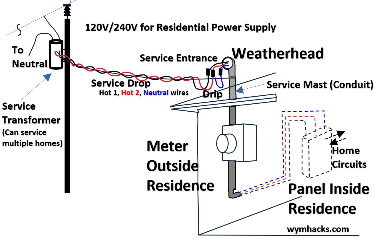
The journey begins with a cable called Triplex.
- It’s called “Triplex” because it comprises three wires twisted together into a single assembly.
- The “Hots” (Phase A and Phase B):
- These are the two insulated aluminum wires.
- Each carries 120V relative to the neutral.
- The “Messenger” (Neutral): This is the bare (uninsulated) aluminum wire in the center.
- The bare wire is the physical “backbone” of the cable.
- It is the only wire under tension; it holds the weight of the entire span so the insulated hot wires don’t stretch and snap.
The Drip Loop and Weatherhead
Picture: Service drop to the House
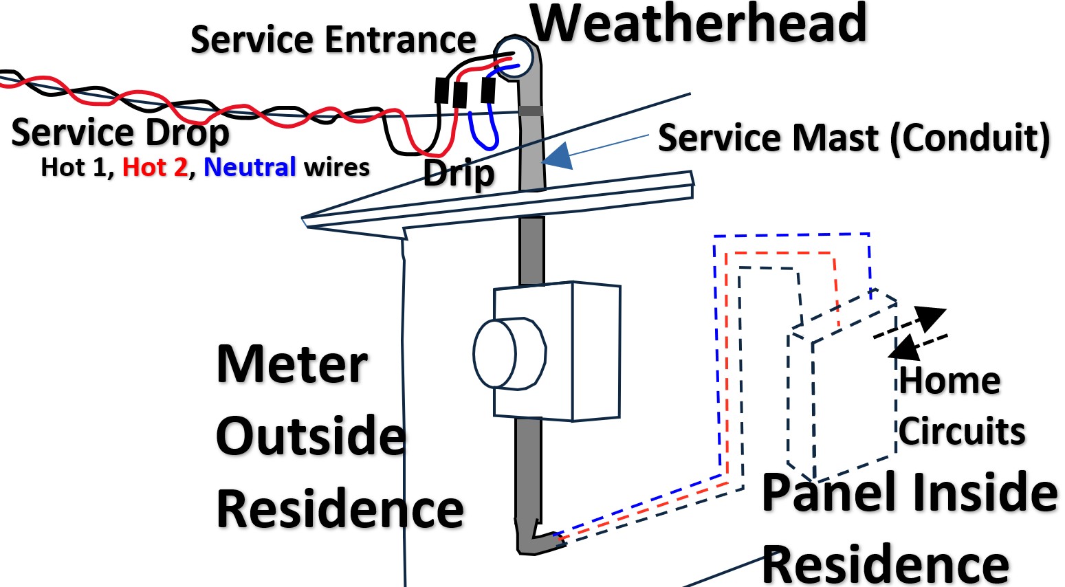
As the Triplex reaches your house, it is anchored to a “dead-end” porcelain insulator.
Here, it transitions into the Service Entrance Conductors owned by you (the homeowner).
- The Drip Loop: The wires are sagged into a “U” shape before entering the pipe.
- Gravity ensures that rain runs to the bottom of the “U” and drips off, rather than following the wire like a slide directly into your electrical panel.
- The Weatherhead (Service Head): This is the “hooded” cap atop your vertical pipe (the Mast).
- Its job is to keep water out while letting the wires enter.
The Mast and Meter Base
The three wires travel down a vertical pipe (the Service Mast) into the Meter Base.
- Inside the meter base, the wires are separated.
- Neutral: Connects to a center lug, which is also “bonded” (connected) to the metal box and a ground rod.
- Hots: Connect to the top lugs of the meter socket.
- When the utility plugs in the Electric Meter, it bridges the top and bottom lugs to begin measuring your usage.
Into the Panel Box
Picture: Residential Meter to Service Panel (Breaker Panel) Connections
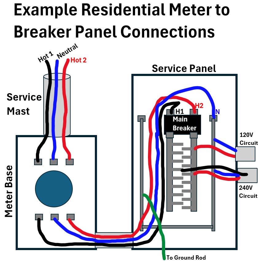
Finally, three thick wires (the Main Feeders) exit the meter and connect to the Main Breaker (Service Panel or Breaker Panel).
- Line 1 (Hot)
- Typical Color: Black
- Panel entry description: Main Breaker (Lug 1)
- Purpose Feeds half of your 120V circuits.
- Line 2 (Hot)
- Typical Color: Red (or Black)
- Panel entry description: Main Breaker (Lug 2)
- Purpose: Feeds the other half of your 120V circuits
- Neutral (using this color because white doesn’t show against white!)
- Typical Color: White (or Taped White)
- Panel entry description: Neutral Bus Bar
- Purpose: The “return path” for all 120V current
wuz: link to home circuit post
Transformer Size or Rating
We’ve mentioned that transformers have an
- kVA = thousands of volt amperes or
- MVA = millions of volt amperes
rating which indicates its size or capacity.
In this section we’ll go through an example of how a transformer is sized to fit your neighborhoods power demands.
But first, I would recommend that
- You have to understand power triangles in order to really understand this section.
- You should read my post on power and power triangles in AC systems : Electrical Power Equations
Power Triangle For AC Circuits
Transformers are rated in kVA or MVA (Apparent Power) because their capacity is limited by heat, which is generated by the total current flowing through their windings—regardless of whether that current is performing “useful” work.
The power triangle illustrates that as your Reactive Power (the magnetizing force for motors or pumps) increases, the Apparent Power also rises, even if your actual wattage remains the same.
If you don’t account for this triangle, you risk overloading the transformer’s thermal limits.
Picture: Power Triangle For Single Phase AC System
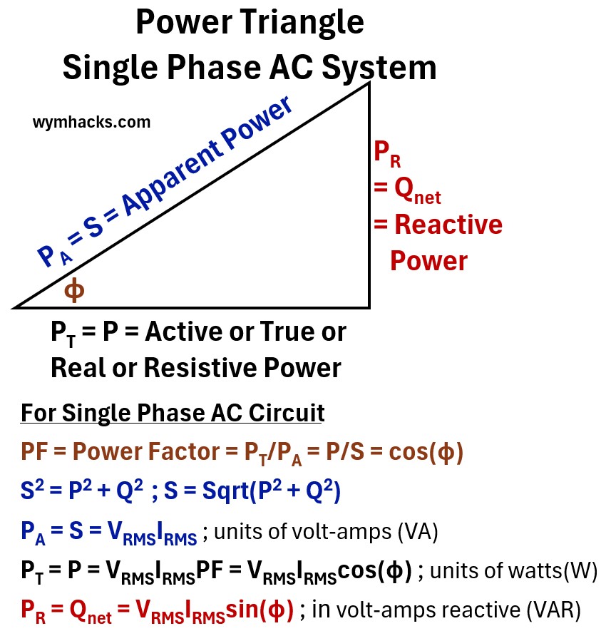
where
PA = S = Apparent Power
- The total “theoretical” power delivered to a circuit, representing the product of voltage and current without considering the timing difference between them
PT = P = Active / True / Real / Resistive Power
- The actual power that performs useful work or generates heat, representing the portion of energy truly consumed by the load.
PR = Qnet = Reactive Power
- The “non-working” power that oscillates back and forth between the source and the load to maintain magnetic or electric fields.
φ = phase angle
- Angular difference between the Voltage sine wave and the Current sine wave.
- The displacement in time, measured in degrees or radians, between the peaks of the voltage and current sine waves.
PF = Power Factor = PT/PA = P/S = cos(φ)
- A ratio between 0 and 1 that represents the efficiency of power usage, calculated as the fraction of apparent power that is converted into real work.
S2 = P2 + Q2 ; S = Sqrt(P2 + Q2)
- The geometric relationship based on the Pythagorean theorem showing that apparent power is the vector sum of real and reactive power.
PA = S = VRMSIRMS ; units of volt-amps (VA)
- The formula for total power capacity measured in volt-amps (VA), calculated by multiplying the effective voltage and current.
PT = P = VRMSIRMSPF = VRMSIRMScos(φ) ; units of watts(W)
- The formula for the actual wattage consumed, which scales the total power by the efficiency of the phase alignment.
PR = Qnet = VRMSIRMSsin(φ) ; in volt-amps reactive (VAR)
- The formula for the reactive power measured in VAR, representing the component of power that is 90 degrees out of sync with the voltage.
VRMS = Root Mean Square Voltage
- The effective AC voltage value that produces the same heating effect as an equivalent DC voltage.
IRMS = Root Mean Square Current
- The effective AC current value representing the steady-state equivalent flow of charge over time.
RMS = Root Mean Square
- A mathematical method used to calculate the “effective” magnitude of a varying waveform, like a sine wave.
- See my post: RMS (Root Mean Square) of a Sinusoid
So the apparent power really represents the total power that will go into useful work and the power involved in the workings of inductors and capacitors.
For example, motors use induction, which requires “borrowing” energy to create magnetic fields.
So, not to beat a dead horse,
- Real Power (P, Watts W or kilo watts = 1000s of watts = kW ): The energy that actually turns the fan or heats the stove.
- Reactive Power (Q, kVAR): The energy vibrating back and forth to maintain magnetic fields.
- Apparent Power (S, kVA): The total sum of both.
The Math: S = √(P2 + Q2). The transformer has to be physically big enough to handle the Total Current (I) required by both, because current is what creates the heat that melts the copper windings.
Example: Transformer Sizing for 5 Houston Homes (3,000 sq. ft. each)
In Houston, sizing is dominated by one thing: The Cooling Load. A 3,000 sq. ft. home typically requires a 5-ton AC unit.
Step 1: The “No-EV” Peak Demand
We estimate the “Connected Load” for a standard 3,000 sq. ft. suburban home:
- General Lighting/Outlets: 9 kW (Based on 3 Watts per sq. ft.).
- Fixed Appliances (Oven, Dryer, Water Heater): 12 kW (Assuming they aren’t all on at once).
- AC Unit (5-ton): 7 kW
- Total Peak Potential: 9 + 12 + 7 = 28 kW per house.
Step 2: The Diversity Factor (DF)
Utilities know that 5 neighbors in Houston aren’t all doing laundry while vacuuming while the AC is at max at the exact same second.
For 5 homes, we use a Diversity Factor of 0.4.
Diversified Load: 28 kW x 5 x 0.4 = 56 kW
Step 3: Convert to kVA
Assuming a standard Power Factor (PF$) of 0.9:
- Calculation: 56 kW / 0.9 = 62.2 kVA.
- Utility Selection: They would likely install a 75 kVA transformer.
- This gives them “headroom” for Houston’s 100 degree F days when the oil struggles to cool down.
What if each house has an electric car charging station?
Now, let’s add one Level 2 EV Charger to each home.
These chargers pull roughly 11.5 kW (48 A at 240V).
The Problem: EVs aren’t “diverse.” Most people plug them in when they get home from work, and they stay on at full power for 8 hours.
The Diversity Factor (DF) for the neighborhood jumps from 0.4 to 0.7.
- New Connected Load: 28 kW per House + 11.5 kW EV = 39.5 kW per house.
- Total Potential: 39.5 kW x 5 = 197.5 kW.
- Convert to kVA: 197.5 / 0.9 = 219.4 kVA.
- Apply New DF (0.7): 219.4 x 0.7 = 153.6 kVA
Result:
- The utility can no longer use a 75 kVA transformer
- They have to jump two sizes up to a 167 kVA transformer.
This is a massive physical and financial jump for the infrastructure.
Makes me think about a few things:
- I think this is why utility infrastructure companies are building dedicated charging stations for cars (I’ve seen several in Houston).
- to ensure that they don’t overwhelm neighborhood transformers.
- But I still see charging stations being installed in homes
- which I believe requires approval and permitting through the infrastructure utility company.
How the Transformer Fuse Set Point is Decided
In this section, we are talking about the “cut out” fuse on the transformer power supply.
This will break open (that handle will break out) if too many amps are flowing in the line.
Picture: Transformer Picture Showing Cut Out Fuse on Power Inlet
![]()
The fuse on the high-voltage side (7200 V “Cutout”) has one main job:
- Protect the grid from a failing transformer.
- It’s the “suicide switch” that prevents a shorted-out transformer from dragging down the whole neighborhood line.
The Math for the Fuse Set Point
Engineers look at the Full Load Current (Ifl) on the high-side.
- For a 75 kVA transformer at $7,200 V:
- Ifl = 75,000 VA/7,200 V = 10.4 amps
- The Set Point Rule:
- Continuous Load: The fuse is usually set at 200% to 300% of the full load current.
- Why? Because when a transformer first turns on, it “gulps” a huge amount of electricity (In rush Current) for a fraction of a second.
- The Choice: For that 10.4 A draw, they would likely use a 20 K or 25 K fuse link.
- The “Slow-Blow”: These fuses are designed to ignore short-term peaks (like your AC starting) but melt instantly if a tree hits the line and the current screams to 100 A.
Ok, you should now have a nice understanding of transformers.
See this post (wuz) if you want to delve a little deeper into household circuits (USA residence).