Three-Phase Electrical Power Generation
When it comes to efficiently powering industry, large buildings, and the electrical grid itself, three-phase circuits are the indispensable workhorses.
The term “phase” refers to a separate stream of alternating current (AC) electricity.
The single-phase power that runs your home’s lights and appliances is typically derived directly from these larger three-phase systems,
- three-phase power itself uses three separate streams of electricity,
- perfectly synchronized but offset by 120 degrees from each other.
The fixed 120° offset ensures the three streams of power (electricity) are perfectly staggered in time.
This angle is a direct result of the physical construction of the three-phase electrical generator (alternator).
Electric Generator
A three-phase electric generator doesn’t use just one set of copper wires (windings); it uses three separate sets of windings—let’s call them A, B, and C.
To generate three distinct, equally spaced voltages, these three windings are physically mounted 120° apart around a central rotating magnetic field.
An electric generator operates on Faraday’s Law of Induction, which states that
- moving a conductor through a magnetic field—or
- changing the magnetic field near a stationary conductor (which is the way power plant generators are designed)
induces an electromotive force (voltage).
As the central magnet rotates, it induces a voltage in each winding.
I cover electric generators in more detail in my blog: Alternating Current (AC) Generation so go there for more info.
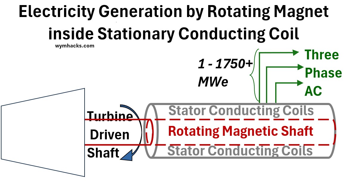
The simplified picture below shows the way these generators are symbolically shown:
- The trapezoid shape is a stream turbine typically or gas turbine which drives a shaft (a rotor)
- which is part of an electric generator.
- The generator consists of a stationary outside system of conducting coils (the Stator)
- and the rotor which has magnetized coils attached to it.
Picture: Simplified Electric Generator Schematic
In the example configuration below I show a cross section of the electric generator with three coils that are configured as pairs in series.
- e.g. Coil A consists of two bundles (A1 and A2) that are series connected and situated opposite each other
- Configurations can get a lot more complicated but the fundamental principles are still true.
Note: Despite the intricate complexity of modern winding patterns, the geometric design of a generator ensures that the final electromagnetic outputs are always offset by a net effective 120 degree “phase” shift.
Picture: 3 Phase AC Generation (120 degree “separation”)
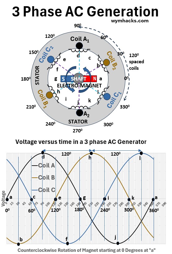
Because the windings are physically separated by 120° in space, the voltage in each winding reaches its peak value at a different time
- When the magnet aligns perfectly with A, Voltage A (VA) peaks.
- The magnet must rotate another 120° of physical space before it aligns perfectly with B, causing VB to peak.
- The magnet must rotate another 120° to cause VC to peak.
This fixed physical separation translates directly into a 120° electrical delay between the three voltage waveforms.
Sinusoidal (Waveform) Voltage Equations
This fixed electrical delay is captured by the phase angle Φ in the voltage equation: V(t) = Vmax cos(ωt + Φ)
Where
- V(t) is voltage expressed as a function of time
- Vmax is the peak voltage (the crest or trough of the sinusoidal graph of voltage vs time)
- ω = angular momentum is radians/second
- t = time in seconds
- Φ = Phase Angle or Phase Shift or Phase Constant
- Φ is a fixed value that determines the starting position of the sinusoidal waveform at time t=0, relative to a reference waveform.
- In the context of three-phase power, Φ is the value that defines the 120° separation between the three different voltage streams.
See my blog on AC Voltage and Current Equations for how this equation is derived.
The three resulting phase voltages are defined by setting the fixed offset Φ for each stream:
VA (Reference) = Vmax cos(ωt + 0°)
- Offset angle Φ = 0°
- Starts at the reference position.
VB (Lagging) = Vmax cos(ωt – 120°)
- Offset angle Φ = -120° = – 2π/3 radians
- Delayed by 120 or 1/3 of a cycle.
VC (Lagging) = Vmax cos(ωt – 240°)
- Offset Angle Φ = -240 degrees = – 4π/3 radians
- Delayed by 240° or 2/3 of a cycle.
The 120° offset is thus the necessary Φ value that reflects the generator’s physical design and ensures the total power output is constant and non-pulsating.
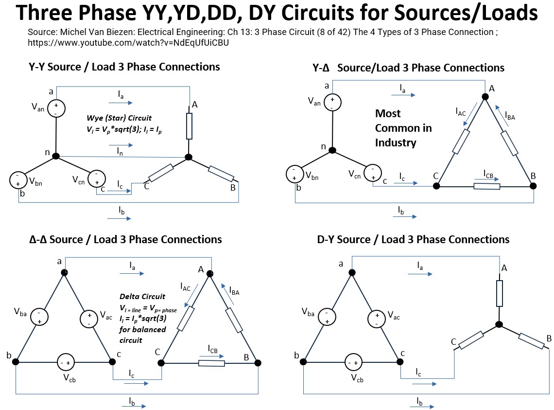
The Two Fundamental 3 Phase Circuit Configurations
To successfully harness this power, both the sources (producers) and the loads (users) must be connected using one of two fundamental configurations:
- The Wye (Y or Star) circuit
- The Delta circuit
These configurations dictate the critical relationships between the electrical quantities
- measured across the components (the phase values) and
- the quantities measured between the main supply lines (the line values).
In the following sections, we will define and explore the specific current and voltage relationships that govern both the Wye and Delta systems.
Wye (Star) Three – Phase Circuit
A Wye (Y) circuit, also known as a Star circuit, is one of the two main ways to configure the components in a three-phase electrical system (the other being a Delta circuit).
It gets its name because the circuit diagram looks like the letter ‘Y’ or a star (see the picture below).
It can be configured as either a Source (where the power comes from, like a generator) or a Load (what the electricity runs, like a motor, or energizes).
The configuration is the same for both.
Wye Circuit Configuration
In a Wye configuration, the three components (whether they are generator windings or load impedances) are connected at one common point, while their other ends are connected to the three transmission lines (conductors or lines).
- Three Phases (A, B, C): These are the three main lines carrying power.
- Neutral Point (N): The single, central point where one end of each of the three phases is joined together.
- Neutral Conductor: A fourth wire often connected to the neutral point. This wire is crucial for providing a return path for current, especially in unbalanced (see Appendix 1) systems.
Picture: Wye (Star) 3 Phase (4 Wire) Circuit – Shown as a Source Circuit (but could be a Load Circuit also)
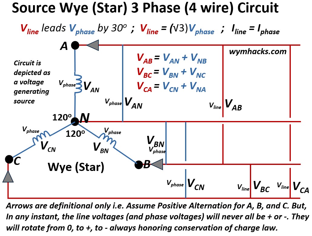
Wye_Circuit Wires
It typically uses a four-wire system: three phase conductors and a neutral wire connected to the star point (it can also be a three-wire system if the neutral is omitted).
Wye_Circuit_Voltages
To find the line voltages in a Wye Circuit like the one shown in the picture above we have to apply Kirchhoff’s Voltage Law (KVL):
- The algebraic sum of all voltages (sources and drops) around any closed path (or loop) in a circuit must equal zero
Note that the drawing shows voltage coming into each node seemingly simultaneously, but that is not what the drawing means.
- It is not telling you anything about what is happening directionally at any instant.
- It is simply establishing the definitions of what “inward versus outward” means.
- Voltage coming “in” is going to be given the positive sign conventionally
- To honor Kirchhoff’s law and the law of conservation of charge, at any instant
- The algebraic sum of all voltages (sources and drops) around any closed path (or loop) in a circuit must equal zero
- i.e. We can never have all three flows being either all negative or all positive.
In a three-phase Wye (Y) circuit, the Line Voltage (Vline ; the voltage measured between any two main lines) is determined by applying KVL using vector addition:
VAB = VAN + VNB = VAN + (-VBN) ; Wye 3 Phase Circuit: Vline
VBC = VBN + VNC = VBN + (-VCN) ; Wye 3 Phase Circuit: Vline
VCA = VCN + VNA = VCN + (-VAN) ; Wye 3 Phase Circuit: Vline
The Line Voltage Vline — measured between any two phase conductors — is √3 (approx. 1.732) times the Phase Voltage Vphase — measured between a phase conductor and the neutral point:
Vline = (√3)Vphase ; Wye 3 Phase Circuit (for balanced system…see appendix 1)
Vline leads Vphase by 300 ; Wye 3 Phase Circuit: Vline
In a later section:
- We’ll get back to the concept of “leading by 30 degrees”,
- and, we’ll show where that √3 factor comes from.
Wye_Circuit_Currents
Iline = Iphase ; Wye 3-Phase Circuit (for balanced system…see Appendix 1)
Wye_Circuit_Use
Wye Circuit Phasor Diagram
A phasor diagram is a visual tool used in electrical engineering, particularly with AC circuits, to represent alternating quantities like voltages and currents as rotating vectors (called phasors).
- It shows the magnitude (length) of the electrical quantity and its phase angle (direction) relative to other quantities or a reference point.
- See this Khan Academy video for an introduction to phasors: Phasor diagram (& its applications)
We can plot the voltages from the KVL equations we derived above onto a vector map using this phasor concept.
- We’ll put the Vphase vector VAN on the positive x axis in the diagram below (this will be our reference point).
Picture: Wye (Star) 3 Phase Circuit Phasor Voltage Diagram
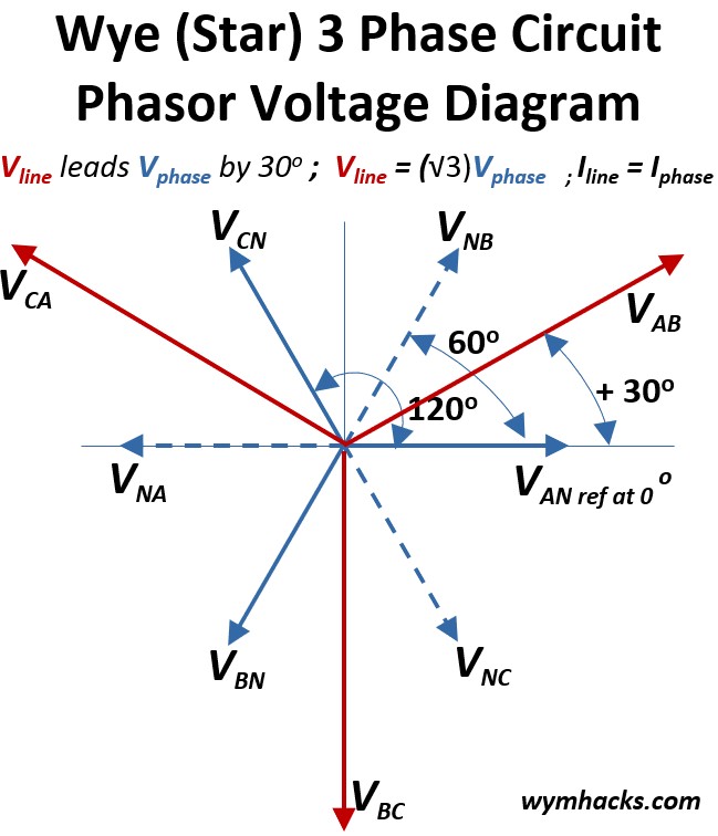
- We can then place the other Vphase vectors VCN and VBN on the diagram because they will be 120 degrees separated from each other.
- Ok, now we want do a little bit of vector addition to plot the line phases VAB , VCA ,VBC
- see my blog on how to add vectors…its easy…Vector Math
Consider VAB = VAN + VNB = VAN + (-VBN) :
- If we add vectors VAN and -VBN (inverse of VNB) we get the vector VAB
- One way to get vector VAB is by taking a copy of VNB and moving its base to the tip of VAN.
- Then draw the VAB vector from the center of the diagram graph (0,0) to the tip of the copy of VNB
- Voila, you get VAB as shown in the diagram above (notice it’s larger than VAN or VNB)
- In fact the magnitude of any of the Vlines will be (√3)(Vphases) = (√3)(inverse Vphases)
- We can follow the same steps to draw vectors VCA and VBC
- If we add vectors VAN and -VBN (inverse of VNB) we get the vector VAB
Recall that Vline leads Vphase by 300
- You can see what this means from the diagram above.
- For Example, from Reference vector VAN, VAB is 300 counterclockwise to it
- i.e. VAB leads VAN by 300
Wye Circuit Line and Phase Voltage √3 Factor Derivation
Let’s show how the line voltage will be √3 x the phase voltage in a Wye circuit.
Below I show the same picture as above with some additional annotations showing the geometry and math.
Picture: Wye (Star) 3 Phase Circuit Sqrt(3) Derivation
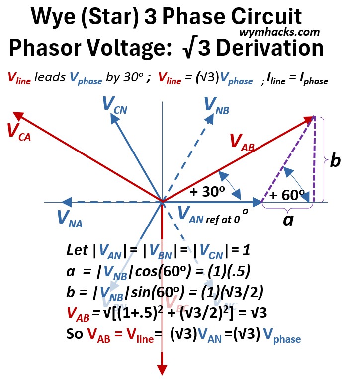
The phase voltages VAN, VBN and VCN (and VNA, VNB, VNC also) will have equal magnitudes so let’s set them equal to 1.
The magnitude of the hypotenuse of the purple dashed line triangle with sides a and b will be equal to the magnitude of VBN = magnitude of VNB
We know sin (θ) = opposite/hypotenuse so sin(60) = b/(VNB) = b/1
We know cos (θ) = cos(60) = adjacent/hypotenuse = a/(VNB) = a/1
If we do the math:
- a = (1)(.5)
- b = (1)(√3/2)
We can now solve for VAB using the Pythagorean Theorem
- (VAB)2 = (b)2 + (a + VAN)2
- VAB = sqrt[ (√3/2)2 + (.5 + 1)2] =√3
So when VAN is 1, VAB is √3 or VAB = √3VAN.
Since VAB is a Vline and VAN is a Vphase ,
Vline = √3Vphase ; Wye 3-phase circuit
That is, the line voltage is about 1.73 (or √3) times the phase voltage.
Wye Balanced Three Phase Circuit Example
In a three-phase system, the arrows used in circuit diagrams represent reference directions, not the physical reality of the current flow at any given millisecond.
While a schematic might show all three current arrows pointing toward the load, the Law of Conservation of Charge (Kirchhoff’s Current Law) dictates that they cannot all be positive simultaneously.
Because the three waveforms are shifted by 120 degrees, the system exists in a state of instantaneous equilibrium;
- at every point in time, the sum of the currents is exactly zero.
- In practice, one or two phases act as the “supply” while the remaining phase(s) act as the “return path,”
- allowing energy to circulate in a perfectly balanced loop without ever violating the fundamental laws of physics.
To demonstrate this, I will examine the specific flow configurations in an example Wye circuit —where currents are positive, negative, or zero.
I’ve used use information from Jim Pytel’s fantastic video to do this
Below is a picture of our example Y circuit,
Picture: Wye Balanced Three Phase Circuit
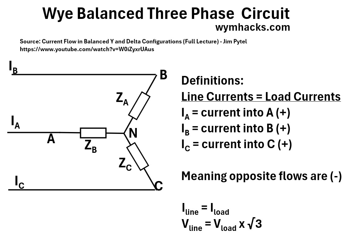
Where we have Line Currents
- IA = current into A (+)
- IB = current into B (+)
- IC = current into C (+)
where (-) means opposite flow
- e.g. – IC = Current out of (from) C
The following voltage and current line and phase relationships hold true
- Iline = Iload
- Vline = Vload x √3
The example values and equations are shown in the picture below
Picture: Wye Balanced Three Phase Circuit (Equations and Values)
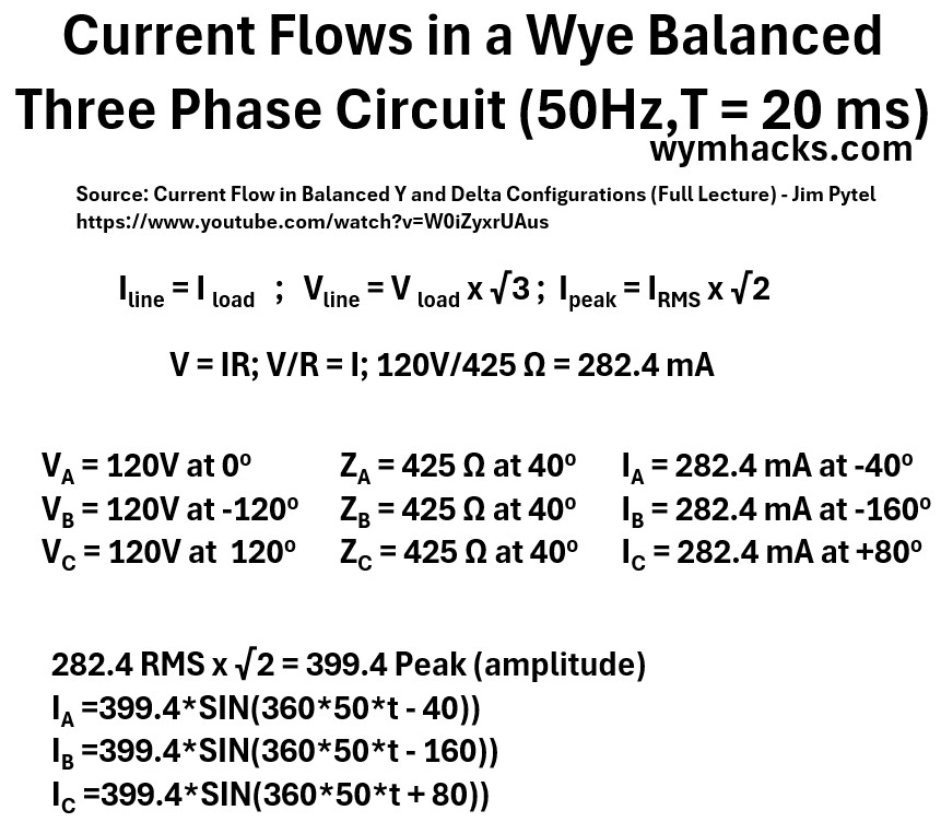
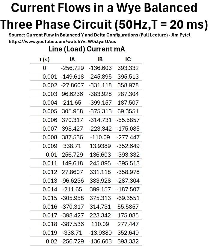
Equations and Values:
- Current Flows in a Wye Balanced Three Phase Circuit at 50Hz and Period T = 20 ms
- Iline = I load
- Vline = V load x √3
- Ipeak = IRMS x √2
- V = IR
- V/R = I;
- 120V/425 Ω = 282.4 mA
- VA = 120V at 00
- VB = 120V at -1200
- VC = 120V at 1200
- ZA = 425 Ω at 400
- ZB = 425 Ω at 400
- ZC = 425 Ω at 400
- IA = 282.4 mA at -400
- IB = 282.4 mA at -1600
- IC = 282.4 mA at +800
- 282.4 RMS x √2 = 399.4 Peak (amplitude)
- IA =399.4*SIN(360*50*t – 40))
- IB =399.4*SIN(360*50*t – 160))
- IC =399.4*SIN(360*50*t + 80))
The table below lists the values of IA,B,C for t = 0 to 20 milliseconds in .001 second steps.
Table: Current Flows in a Wye Balanced Three Phase Circuit
Below we Graph the values above, giving us a beautiful set of sinusoid waves moving through one period.
Graph: Current Flow: Wye Balanced Three Phase Circuit
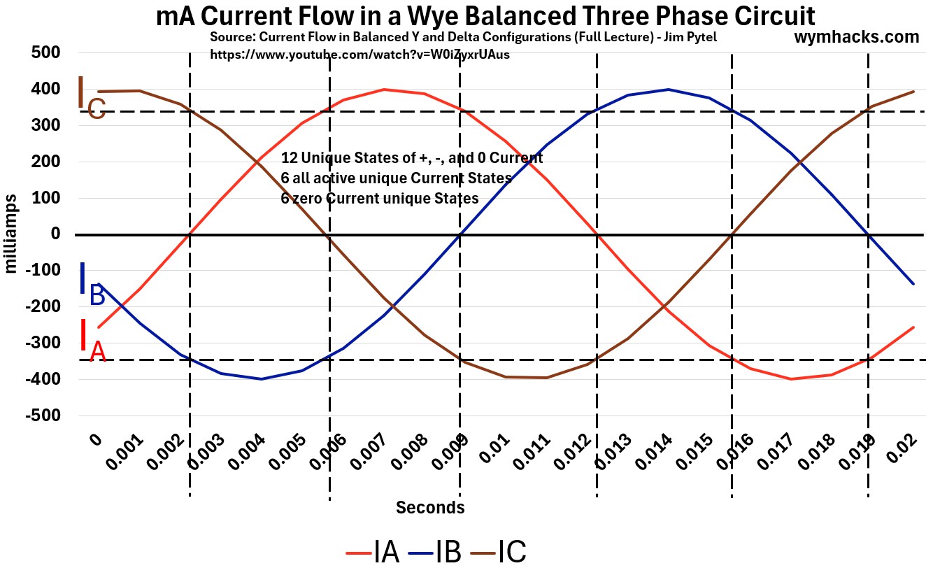
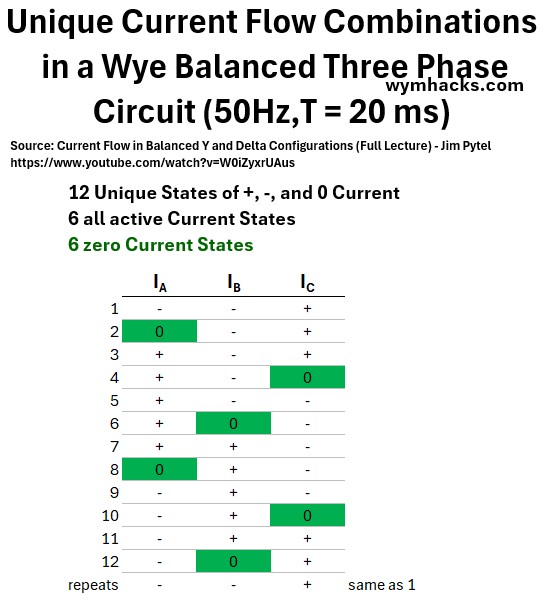
In the table below I show the 12 unique flow “configurations” that this circuit can produce.
Each one honors the “what goes in must come out” energy principle (law of conservation of energy).
- i.e. you always have to satisfy the material (energy) balance.
You can use the graph above to convince yourself that this is true.
Table: Unique Current Flow Combinations in a Wye Balanced Three Phase Circuit
Delta Three – Phase Circuit
The Delta circuit (Δ) is the counterpart to the Wye (Y) circuit, and it has unique characteristics that make it suitable for different applications.
A Delta (Δ) configuration is a way of connecting three sources (like generator coils) or three loads (like motor windings or heating elements) end-to-end to form a closed triangular loop.
It gets its name from its resemblance to the Greek letter Delta Δ.
Delta Circuit Configuration
- With sources: Each of the three generator windings is connected in series with the others to form a closed triangle.
- With loads: Each of the three load impedances is connected in series with the others to form a closed triangle.
- Three Wires: Power is tapped directly from the three junction points (corners) of the triangle.
- No Neutral: Unlike a Wye circuit, a standard Delta connection does not have a neutral point to return to.
- This means it is typically a three-wire system (A, B, C)
For a balanced (see Appendix 1) Delta circuit, the relationships between the Line quantities (measured in the main wires) and the Phase quantities (measured across a single component) are the opposite of the Wye circuit.
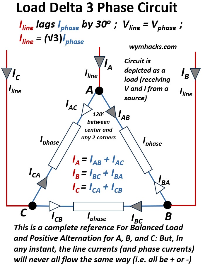
Picture: Delta 3 Phase Circuit Diagram (shown as a load circuit)
Delta Circuit Voltage
In a Delta connection, each phase component (source winding or load impedance) is connected directly across two line conductors.
This means the voltage measured across the phase component is the same as the voltage measured between the two lines.
Vline = Vphase ; Delta 3-Phase Circuit (for balanced system…See Appendix 1)
Delta Circuit Current
The above Delta circuit drawing seemingly shows line current and phase current flows (greyed arrows) all going in the same direction simultaneously.
That is not what the drawing means. That would violate the law of conservation of charge.
- The drawing is simply establishing the definitions of the current direction, being positive when it is coming into the node.
- At any given instant the line currents will never be aligned the same way (all + or all -)
- At any given instant the phase current will never all be + or –
To find the line currents in a Delta Circuit like the one shown in the picture above we have to apply Kirchhoff’s Current Law (KCL):
- At any corner of the Delta connection, the Line Current, Iline , flowing in from the main conductor must equal the vector sum of the two Phase Currents Iphase flowing out into the two connected load impedances.
The Line Current vectors are therefore:
IA = IAB + IAC ; Delta 3-Phase Circuit: Iline
IB = IBC + IBA ; Delta 3-Phase Circuit: Iline
IC = ICA + ICB ; Delta 3-Phase Circuit: Iline
The Line Current Iline — measured between any two phase conductors — is √3 (approx. 1.732) times the Phase Current Iphase — measured between a phase conductor and the neutral point:
Iline = (√3)Iphase ; Delta 3-Phase Load Circuit Current (for balanced system…See Appendix 1)
Iline lags Iphase by 300 ; Delta 3-Phase Load Circuit Current
In a later section,
- we’ll get back to the concept of lagging by 30 degrees and
- where the √3 factor comes from.
Wires
No neutral wire is typically available. (so 3 wires)
Use
Delta connections are often used in transmission systems and to supply three-phase motor loads because they deliver high line voltage and don’t require a neutral conductor.
Delta Phasor Diagram
A phasor diagram is a visual tool used in electrical engineering, particularly with AC circuits, to represent alternating quantities like voltages and currents as rotating vectors (called phasors).
- It shows the magnitude (length) of the electrical quantity and its phase angle (direction) relative to other quantities or a reference point.
- See this Khan Academy video for an introduction to phasors: Phasor diagram (& its applications)
We can plot the currents from the KCL equations we derived above onto a vector map using this phasor concept.
- We’ll put the Iphase vector IAB on the positive x axis in the diagram below (this will be our reference point).
Picture: Delta 3-Phase Circuit Phasor Current Diagram
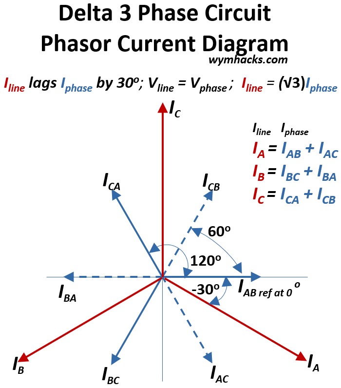
- We can then place the other Iphase vectors ICA and IBC on the diagram because they will be 120 degrees separated from each others
- Ok, now we want do a little bit of vector addition to plot the line phases IA , IB , IC
- (see my blog on how to add vectors…its easy…Vector Math)
Consider IA = IAB + IAC ; Delta 3-Phase Load Circuit
- If we add vectors IAB and -ICA (inverse of IAC) we get the vector IA
- One way to get vector IA is by taking a copy of IAC and moving its base to the tip of IAB.
- Then draw the IA vector from the center of the diagram graph (0,0) to the tip of the copy of IAC
- Voila, you get IA as shown in the diagram above (notice it’s larger than IAC or IAB)
- In fact the magnitude of any of the Ilines will be (√3)(Iphases) = (√3)(inverse Iphases)
- We can follow the same steps to get vectors IB and IC
- If we add vectors IAB and -ICA (inverse of IAC) we get the vector IA
Recall that Iline lags Iphase by 300
- You can see what this means from the diagram above.
- For Example, from Reference vector IAB, IB is 300 clockwise to it
- i.e. IA lags IAB by 300
Delta Circuit Line and Phase Current √3 Factor Derivation
With a little bit of geometry and trig. we can show that, in a Delta circuit, the line current is equal to √3 x the phase current.
The picture below is an annotated version of the picture above showing the geometry and math involved in the derivation.
Picture: Delta 3 Phase Circuit Phasor Current: √3 Derivation
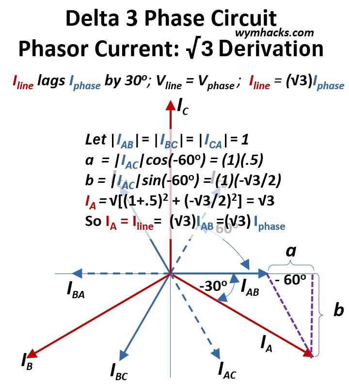
The phase currents IAB, IBC and ICA (and IBA, ICB, IAC also) will have equal magnitudes so let’s set them equal to 1.
The magnitude of the hypotenuse of the purple triangle with sides a and b will be equal to the magnitude of IAC = magnitude of ICA
We know sin (θ) = opposite/hypotenuse so sin(-60) = b/(IAC) = b/1
We know cos (θ) = cos(-60) = adjacent/hypotenuse = a/(IAC) = a/1
If we do the math:
- a = (1)(.5)
- b = (1)(-√3/2)
We can now solve for IA using the Pythagorean Theorem
- (IA)2 = (b)2 + (a + IAB)2
- IA = sqrt[ (-√3/2)2 + (.5 + 1)2] =√3
So when IAB is 1, IA is √3 or IA = √3IAB.
Since IA is a Iline and IAB is a Iphase ,
Iline = √3Iphase ; Delta 3-phase circuit
That is, the line current is about 1.73 (√3) times the phase current.
Delta Balanced Three Phase Circuit Example
In a three-phase system, the arrows used in circuit diagrams represent reference directions, not the physical reality of the current flow at any given millisecond.
While a schematic might show all three current arrows pointing toward the load, the Law of Conservation of Charge (Kirchhoff’s Current Law) dictates that they cannot all be positive simultaneously.
Because the three waveforms are shifted by 120 degrees, the system exists in a state of instantaneous equilibrium;
- at every point in time, the sum of the currents is exactly zero.
- In practice, one or two phases act as the “supply” while the remaining phase(s) act as the “return path,”
- allowing energy to circulate in a perfectly balanced loop without ever violating the fundamental laws of physics.
To demonstrate this, I will examine the specific flow configurations in an example Delta circuit —where currents are positive, negative, or zero.
I’ve used use information from Jim Pytel’s fantastic video to do this
Below is a picture of our example Delta circuit,
Picture: Delta Balanced Three Phase Circuit
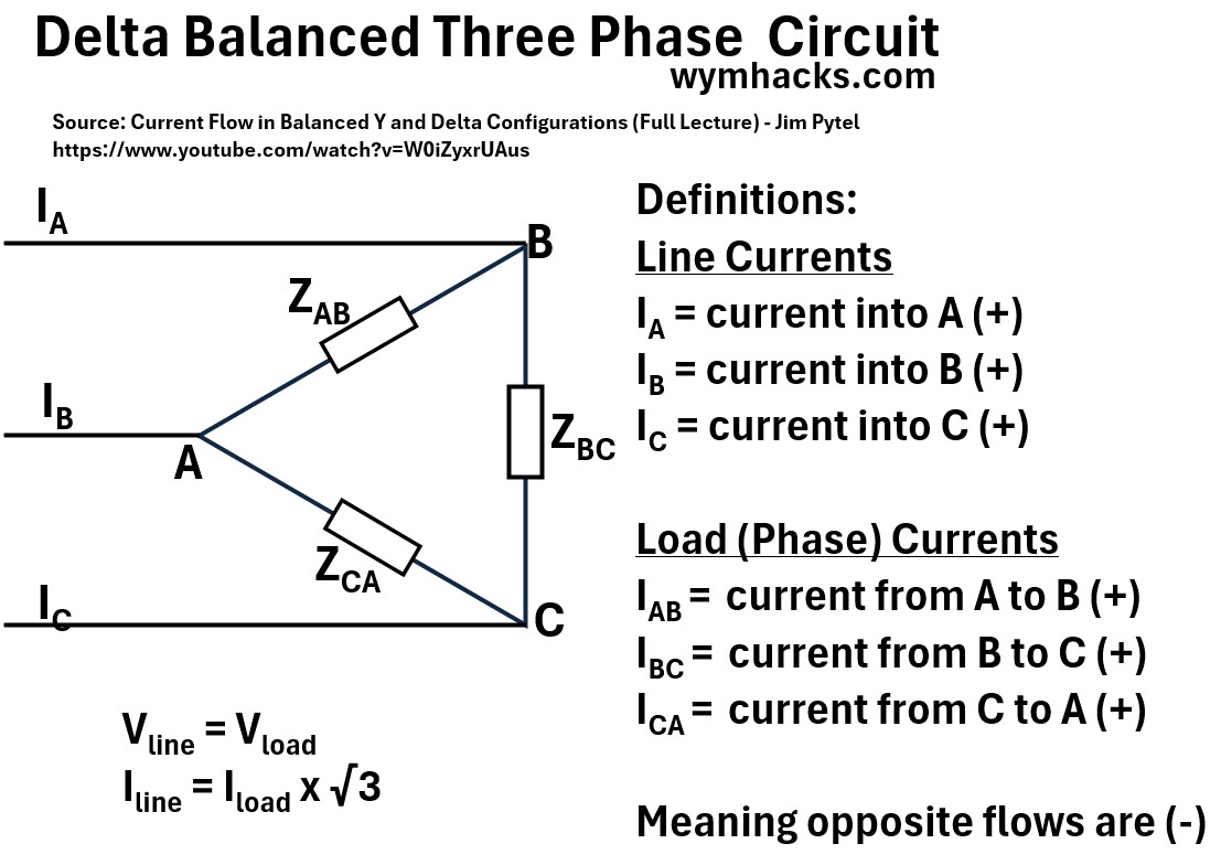
Where we have Line Currents,
- IA = current into A (+)
- IB = current into B (+)
- IC = current into C (+)
and Load (Phase) Currents
IAB = current from A to B (+)
IBC = current from B to C (+)
ICA = current from C to A (+)
where (-) means opposite flow
- e.g. – ICA = IAC = current from A to C
- e.g. – IC = current from C
The following voltage and current line and phase relationships hold true
- Vline= Vload
- Iline = Iload x √3
The example values and equations are shown in the picture below
Picture: Delta Balanced Three Phase Circuit (Equations and Values)
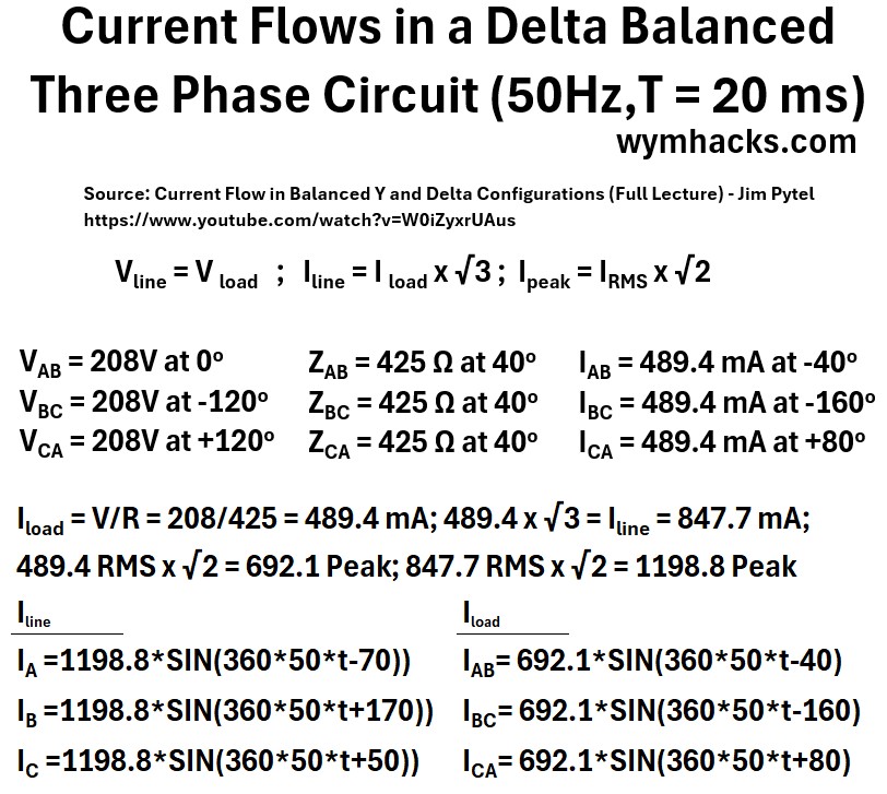
Equations and Values:
- Current Flows in a Delta Balanced Three Phase Circuit at 50Hz and period T = 20 ms
- Vline = Vload ;
- Iline = Iload x √3 ;
- Ipeak = IRMS x √2
- VAB = 208V at 00
VBC = 208V at -1200
VCA = 208V at +1200 - ZAB = 425 Ω at 400
ZBC = 425 Ω at 400
ZCA = 425 Ω at 400 - IAB = 489.4 mA at -400
IBC = 489.4 mA at -1600
ICA = 489.4 mA at +800 - Iload = V/R = 208/425 = 489.4 mA; 489.4 x √3 = Iline = 847.7 mA;
- 489.4 RMS x √2 = 692.1 Peak; 847.7 RMS x √2 = 1198.8 Peak
- Iline
- IA =1198.8*SIN(360*50*t-70))
- IB =1198.8*SIN(360*50*t+170))
- IC =1198.8*SIN(360*50*t+50))
- Iload
- IAB= 692.1*SIN(360*50*t-40)
- IBC= 692.1*SIN(360*50*t-160)
- ICA= 692.1*SIN(360*50*t+80)
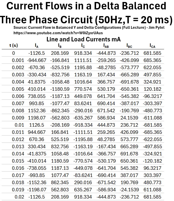
The table below lists the values of IA,B,C and IAB,BC,CA for t = 0 to 20 milliseconds in .001 second steps.
Table: Current Flows in a Delta Balanced Three Phase Circuit
Below we Graph the values tabulated above, giving us a beautiful set of sinusoid waves moving through one period.
Graph: Current Flow: Delta Balanced Three Phase Circuit
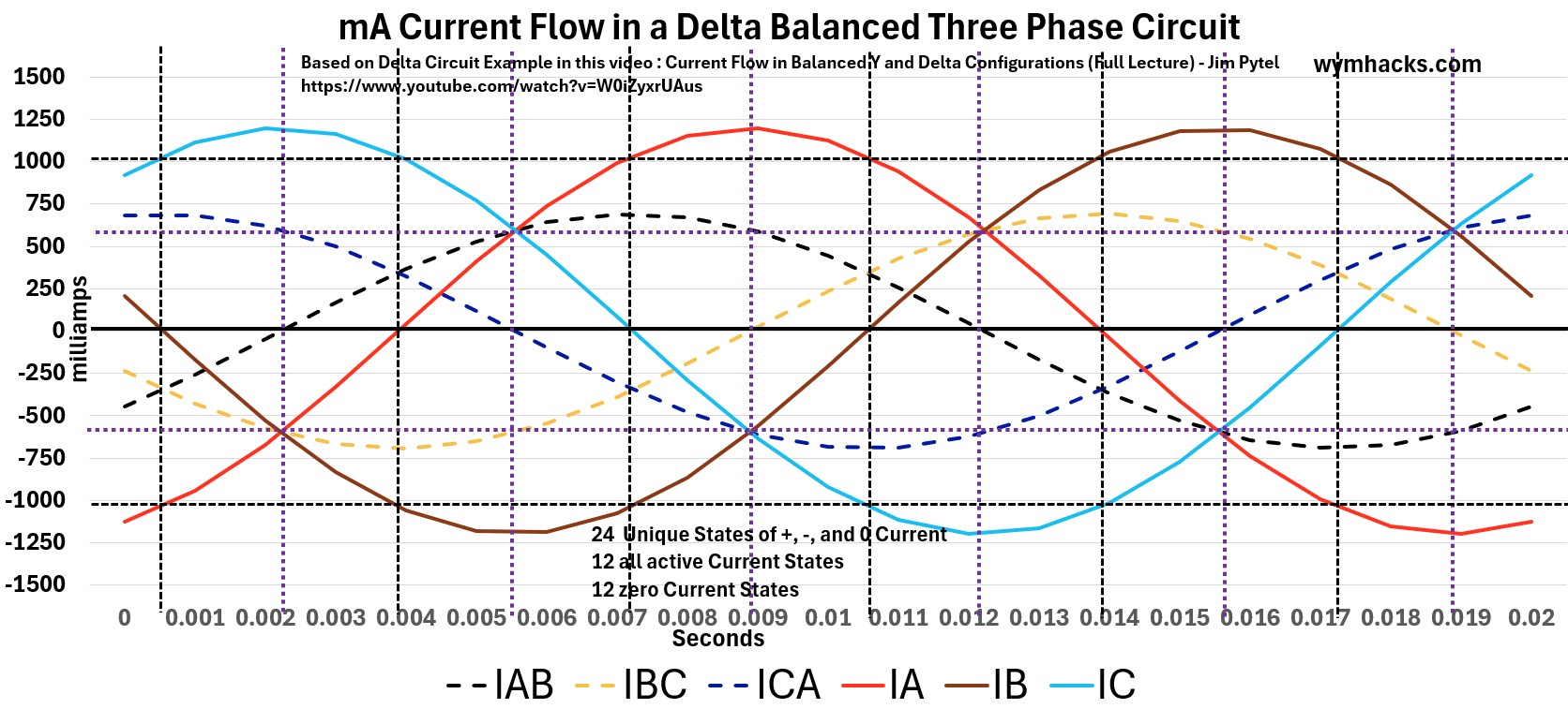
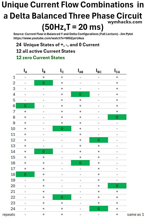
In the table below I show the 24 unique flow “configurations” that this circuit can produce.
Each one honors the “what goes in must come out” energy principle (law of conservation of energy).
- i.e. you always have to satisfy the material (energy) balance.
You can use the graph above to convince yourself that this is true.
Table: Unique Current Flow Combinations in a Delta Balanced Three Phase Circuit
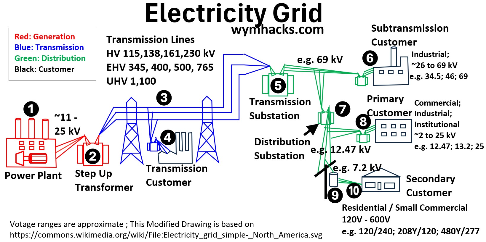
Wye and Delta Circuits Along the Grid
As power moves through the grid, here is a breakdown of the typical circuit configurations along that path, including a few technical nuances that often appear in these standard setups.
The Power Plant Electric Generator (Wye Circuit)
Large generators are almost always Wye-connected to provide a neutral point.
- This neutral is grounded which allows engineers to easily detect and protect against internal ground faults.
- It also handles the mechanical stress of unbalanced forces better than a Delta winding
Step-Up Transformer (Delta-Wye)
Primary Coil (Generator side): Delta
Secondary Coil (Grid side): Wye (Grounded-Y)
The Delta primary “traps” 3rd harmonic currents within the transformer, preventing them from polluting the grid.
- i.e. The Delta connection acts like a circular track that keeps certain electrical “noise” spinning in a loop inside the transformer so it can’t escape into the outside power lines.
The Wye secondary on the high-voltage side provides a solid ground reference for the transmission lines and allows for cheaper insulation since the voltage from any phase to ground is only 1/sqrt(3) (about 58%) of the phase-to-phase voltage.
High-Voltage Transmission Line (3 Wire Delta Style)
Configuration: 3-Wire Delta-style
Why: Even though the source (Step-Up transformer secondary coil) is Wye, we only carry the three phase wires (A, B, C) over long distances.
- Carrying a neutral wire for hundreds of miles is expensive and unnecessary because the phases are kept balanced.
- Grounding is handled at each end.
Takeoffs to Transmission Customers (Wye_Wye or Delta_Wye)
Configuration: Wye_Wye (Y-Y) or Delta_Wye (Delta-Y)
Large industrial customers usually receive 3-wire power.
If they have their own substation, they often use a Delta-Wye setup so they can create their own grounded neutral for their internal factory equipment.
Substation Step-Down Transformer (Delta_Wye)
Primary Coil (High Voltage Side side): Delta
Secondary Coil (Medium Voltage side): Grounded Wye (Y)
This is the most common “Utility Standard.”
The Delta primary accepts the 3-wire transmission feed.
The Wye secondary creates the neutral wire needed for the next few stages of distribution.
Sub-transmission Customers
- These customers are often smaller industrial plants or large campuses.
- Configuration: Typically a three wire supply feeds these customer’s transformer/s.
- They typically use Delta primaries on their equipment to remain isolated from the utility’s grounding system while receiving high-power three-phase service.
- So transformers will typically have a Delta_Wye circuit configuration.
Primary Distribution Customers
Transformer Configuration: Delta-Wye
At this “neighborhood” level, the transformer usually has a Delta primary (taking 3 wires from the pole) and a Wye secondary.
This allows the utility to serve both 3-phase commercial loads (like a grocery store’s refrigeration) and 1-phase residential loads from the same transformer.
Secondary Customer
Configuration: Single-Phase Center-Tapped (Split-Phase)
In North America, the “transformer on the pole” near your house is actually a single-phase transformer.
Primary: Connected between one phase and the neutral of the 13kV line.
Secondary: A single coil with a Center Tap. The center tap is grounded (Neutral), giving you 120V from either end to the center, and 240V between the two “hot” ends.
When we talk about Wye and Delta, we are describing the “shape” of the wiring.
In three-phase AC systems, we always discuss them in pairs because a transformer has two separate sides: an input (Primary) and an output (Secondary).
Think of these pairs like a language translation. The pair tells you what “language” the electricity is speaking when it enters the transformer and what “language” it speaks when it leaves.