Simple Electric Circuit
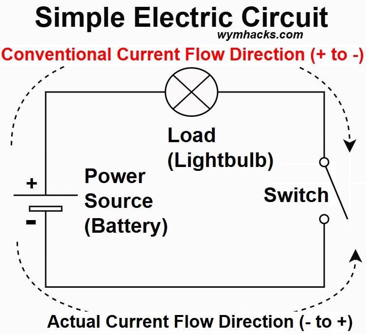
A basic electrical circuit is a closed loop system that allows electricity to flow and do useful work.
In the picture below, a source of electricity (a battery) provides current (electrons) through a switch to a light bulb and then back to the battery.
Picture – Simple Electric Circuit
A circuit , at a minimum, needs the following:
A Power Supply
A power supply
- like an electric generator in a power plant or
- a battery (in your flashlight for example).
provides the push (voltage) that electrons need in order to move (current) to their intended end use.
The power source (supply) is like a pump in a water system.
Conductors
The wire carrying the electricity from its source to its users is a conductor of electricity.
Conductors would be analogous to the pipes in a water system.
Conductors are typically made of copper and
- provide an easy path for the electricity to flow
- from the power source to where it’s needed
- and back again.
A Load
A load is the device that uses the electrical energy by converting it into another form of energy like
- light (e.g. light bulbs),
- heat (e.g. oven, or
- motion (e.g. motors)
A Closed Loop
The electron flow pathway must be complete and unbroken (i.e. a loop).
In our drawing, an open switch would prevent the electrons from flowing.
In summary, at the very minimum, for a circuit to work properly,
- a power source must “push” electricity through the conductors,
- which goes through a load that performs a task, and
- then returns to the power source, completing the loop.
Type of Circuit Elements
Electrical circuits consist of two main categories of elements: passive and active.
Passive Elements
Passive elements are components that cannot generate power on their own.
- They either dissipate, store, or otherwise manage electrical energy.
Examples include:
Resistors: These Oppose current flow, dissipating energy as heat. Examples include
- Kitchen Toasters & Ovens Converts electricity into intense heat to cook food.
- Kitchen Electric Kettles A submerged element that heats water via resistance.
- Personal Care Hair Dryers A glowing wire coil that heats air blown past it.
- Electronics LED Indicators Limits current so the tiny light doesn’t “pop.”
- Electronics Volume Knobs A variable resistor that dims the audio signal.
- Home Safety Digital Thermostats A thermistor that changes resistance based on air temp.
- Lighting Incandescent Bulbs A tungsten filament that resists current until it glows.
- Automotive Rear Defrosters Thin resistive lines on glass that melt ice with heat.
Capacitors: Store energy in an electric field.
- Camera Flashes: A battery isn’t strong enough to create that blinding white light instantly.
- A capacitor “soaks up” energy from the battery slowly and then dumps it all into the bulb in a fraction of a second.
- AC Units & Washing Machines (Start Capacitors): Motors in heavy appliances need a massive “shove” to start spinning from a dead stop.
- A large capacitor provides that initial jolt of torque.
- Computer Keyboards: Underneath the keys of many high-end keyboards are “capacitive sensors.”
- When you press a key, you change the distance between two metal plates, which changes the capacitance, telling the computer which letter you typed.
- Touchscreens: Your smartphone screen is a giant capacitor.
- When your finger (which conducts electricity) touches the glass, it “steals” a tiny bit of the electric field. The phone calculates exactly where that field changed.
- Power Smoothing: If you’ve ever noticed your lights flicker for a millisecond, capacitors in your electronics (like your TV) “fill the gap.”
- They hold enough charge to keep the device running during tiny micro-drops in power.
- Filtering Noise: In audio equipment, capacitors are used to block “hum” or static.
- They allow high-frequency sounds to pass through while blocking low-frequency “thumps” (or vice versa).
- Memory Backup: In some devices, a “supercapacitor” holds enough juice to keep the internal clock running even when you pull the plug or the battery dies.
- Camera Flashes: A battery isn’t strong enough to create that blinding white light instantly.
Inductors: Store energy in a magnetic field.
- Electric Motors (Fans, Blenders, Washers): Every motor contains large coils of wire.
- When electricity flows through them, they create a magnetic field that pushes the motor’s rotor, turning electrical energy into motion.
- Microwaves & Doorphones: These use Transformers, which are just two inductors placed next to each other.
- One “induces” a voltage into the other via magnetism to change the power level.
- Wireless Chargers: Your phone and the charging pad both have flat inductive coils.
- The pad creates a magnetic field, and the phone’s coil “catches” it to turn it back into electricity.
- In smaller circuits, inductors act as “filters” or “energy buckets.”
- Speakers & Headphones: A coil of wire (an inductor) is attached to the speaker cone.
- As the signal changes, the magnetic field moves the cone back and forth to create sound waves.
- Power Supplies: Inductors are used to “smooth out” electricity.
- If the power spikes, the inductor’s magnetic field absorbs the extra; if it drops, the field collapses and “pushes” some energy back into the line.
- Radio & Cell Phones: Inductors, paired with capacitors, allow your device to “tune” into a specific frequency (like 94.1 FM or a 5G band) while ignoring all others.
- Speakers & Headphones: A coil of wire (an inductor) is attached to the speaker cone.
- Electric Motors (Fans, Blenders, Washers): Every motor contains large coils of wire.
- Transformers: Transfer energy between circuits through magnetic coupling.
- Voltage can be stepped up or down via transformers. See my post: Transformers
Active Elements
Active elements are components that can control or generate electrical energy, often requiring an external power source to operate.
- They can amplify signals or switch currents.
Examples include:
- Transistors: Act as electronic switches or amplifiers.
- Diodes: Allow current to flow in only one direction.
- Operational Amplifiers (Op-Amps): High-gain voltage amplifiers.
- Voltage and Current Sources: Provide a constant voltage or current to a circuit.
Electric Resistance and Ohm’s Law (V = IR)
Resistance and Resistivity
In a circuit, resistance is the opposition that a material or component offers to the flow of electric current.
R = resistance = ohms = Ω
SI unit (base units): (m2kg)/(s3A2)
SI unit (other SI units): Volts/Ampere = V/A
R = resistance = ρL/A
- ρ (rho) = resistivity of the material (in ohm-meters, Ω⋅m).
- Resistivity is an intrinsic property of the material that indicates how strongly it opposes electric current.
- Different materials have different resistivities.
- L is the length of the conductor (in meters, m).
- A is the cross-sectional area of the conductor (in square meters, m2).
- Beware, A can also be used as a symbol for the ampere unit.
Resistor
Passive components only consume, store, or dissipate the energy supplied to them by the circuit.
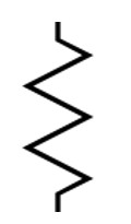
A resistor is a passive electronic component that limits or opposes the flow of electric current in a circuit, converting electrical energy into heat.
Picture: Resistor Circuit Element Symbol
Conductance
Conductance is the inverse of resistivity which makes sense.
Conductance = σ = 1/ρ
Material Resistivity (ρ) Examples
Copper is a low resistivity (high conductance) material:
- Copper is a metal with a large number of free electrons that can move easily, allowing electric current to flow with very little opposition.
- It is an excellent conductor.
- Copper is the most widely used material for electrical wiring in homes, buildings, and power distribution systems.
- Its low resistivity makes it very efficient with minimal energy losses (used in motor windings and transformers).
- Due to its lighter weight and lower cost (compared to Copper), Aluminum is the dominant material for high-voltage overhead transmission lines
Porcelain is a ceramic material with a high resistivity (low conductivity): or higher
- Porcelain has a tightly bound atomic structure and very few free electrons making it an excellent electrical insulator.
- It’s extensively used
- as an insulator on power transmission lines and in substations (prevents high voltage electricity from flowing to supporting structures)
- as bushings where conductors pass through enclosures, providing insulation from the case.
- in components found in electrical devices where high electrical insulation and mechanical strength are required.
Ohms Law
The resistance of a material plays a big role in the relationship of voltage to current in a circuit.,
Voltage = Current * Resistance = V = IR ; Resistor Element Equation
1 Volt is the electrical potential difference across a conductor when a current of 1 ampere flows through a resistance of 1 ohm.
- I = current comes from the French description of “intensity” of current.
- V = voltage
- SI unit for voltage (base units): (m2kg)/(s3A)
- SI unit for voltage (other SI units): W/A = J/C
- SI Units for current: C/s
- SI units for charge C: As
- R = Resistance = ohms = Ω
- SI unit for Resistance (base units): (m2kg)/(s3A2)
- SI unit for Resistance (other SI units): V/A
- SI unit for Resistance (other SI units): Js/C2
Ohmic vs Non-Ohmic Materials
From Ohm’s Law we can express R as: R = V/I
But be careful how you interpret this.
- Since R will be constant for many materials of interest in electrical engineering, you cannot assume that adjusting V or I will change R.
- In fact if you change V or I with the same material of resistance R, then the other variable will adjust to main the value of R.
If R is constant we say the material is ohmic and follows Ohm’s Law.
We can verify if this is true by graphing V versus I for a material.
- If the result is a straight line then R is constant and the material obeys Ohm’s Law.
- You can compute R by simply dividing I into V at any point
Some notable non-ohmic materials are:
- Semiconductor Devices (Diodes, Transistors, LEDs, Thermistors, Varistors) are non ohmic materials.
- Incandescent Light Bulbs (Filament Lamps): the resistance of the bulb increases as it gets hotter.
- Neon lamps and fluorescent tubes
- Some Electrolytes
Watch these nice videos on resistivity, conductivity, and Ohm’s law:
Resistors in Parallel and in Series
Series Resistors
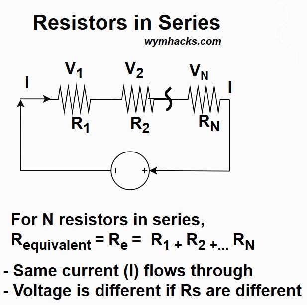
Resistors that are connected end to end are described as resistors in a series configuration.
For resistors in series:
- Current (I) is the same: The same current flows through every resistor in the series (conservation of charge).
- Voltage (V) divides: The total voltage supplied by the source is split among the resistors.
- Depends on Ohm’s Law ().
- Resistance adds: The total equivalent resistance of the series circuit is the sum of all individual resistances ().
- Adding more resistors in series increases the overall resistance.
For N Resistors in Series: Requivalent = Re= R1+R2…+RN
Picture: Resistors in Series
If you had a simple circuit containing a series of resistors and you were given
- the source voltage V and
- the resistances of each of the resistors R
you could calculate the current and the voltages across each resistor using Ohm’s Law V=IR (Voltage = Current × Resistance):
See this nice video with an example:
Resistors in Series – Khanacademy – Willy McAllister
Parallel Resistors
Picture: Resistors in Parallel
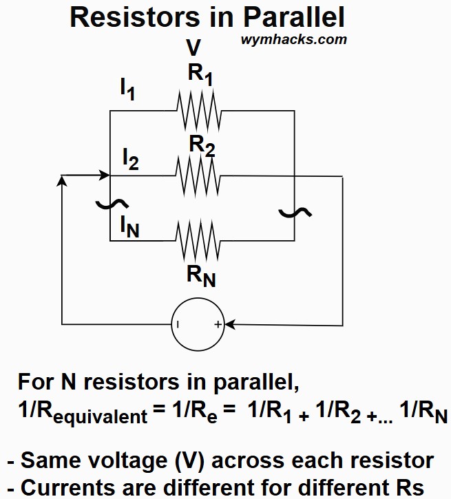
Resistors are in parallel when both ends of all the resistors are connected to a pair of common points, providing multiple paths for the current to flow.
- i.e. in the picture above, there is common node feeding all three resistors and there is a common node accepting the flow from all three resistors.
Current () divides: The total current is divided among the branches.
The current is greater through the resistor with the smaller resistance.
Voltage () is the same: The same voltage (potential difference) is applied across every resistor
Resistance reduces (): The reciprocal of the total resistance is the sum of the reciprocals of the individual resistances.
For N Resistors in Parallel: 1/Requivalent = 1/Re= 1/R1+1/R2…+1/RN
Adding resistors in parallel decreases the total resistance,
- thereby increasing the total current drawn from the source.
- The equivalent resistance is always less than the smallest individual resistance.
Product Over Sum Rule (For Two Resistors)
If you have two resistors, and , in parallel, their equivalent resistance () can be calculated directly as:
For 2 Resistors in Parallel: Re =(R1)(R2)/(R1+ R2)
This “Product Over Sum” rule is a popular shortcut because it is quicker to calculate than the standard formula when dealing with only two components.
If you have three or more resistors, you must use the standard reciprocal method or apply the product over sum rule repeatedly to pairs of resistors.
Resistors in Parallel – Khanacademy – Willy McAllister
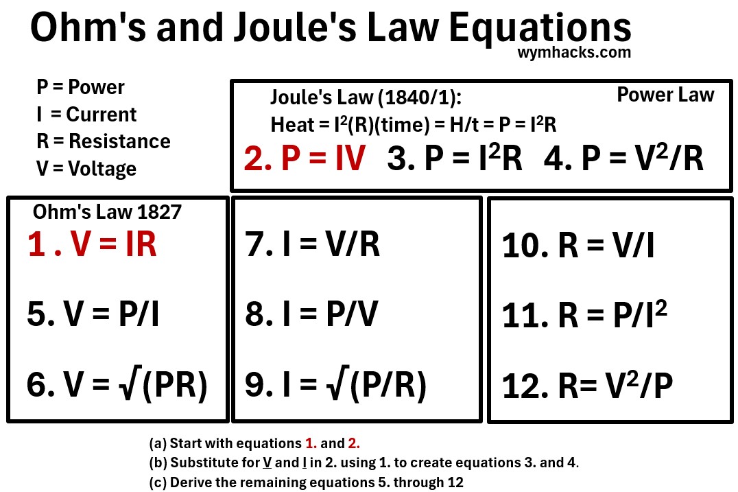
P, I, R, V Relationships
There are 12 relationships among Power, Current, Resistance, and Voltage that you should know.
We’ll develop them in this section.
Recall Ohms law which states that the current through a conductor between two points is
- directly proportional to the voltage across the two points, and
- inversely proportional to the resistance between them.
1. V = IR (Ohm’s Law)
where
- V = voltage where 1 V = 1 m2kgs-3A-1 = 1 Watt/A = 1 W/A = 1 Joule/C = 1 J/C
- R = resistance where 1 Ω = 1 m2kgs-3A-2 = 1 V/A
- I = current where 1 Amp = 1 A = 1 Coulombs/second = 1 C/s
Ohm came up with this in 1827.
Fast forward about 13 years to 1840/1 and we have James Prescott Joule developing another relationship.
Joule’s Law, determined empirically, states that:
the heat (energy) generated (H) in a conductor is directly proportional to
- the square of the current () flowing through it,
- the electrical resistance () of the conductor, and
the time () for which the current flows
where
- H = heat energy in Joules (J) where 1 J = 1 Nm = 1 m2kgs-2
Heat = I2(R)(time)
Divide t into both sides and recognize that H/t = energy/t= Power Dissipated (turned into heat) = Pheat. So,
2. H/t = Power = Pheat = I2R (Joule’s Law in Power form)
where
- Pheat = Power Dissipated (turned into heat) in a resistive component where 1 watt = 1 W = 1 m2kgs-3 = 1 J/s
- It is frequently associated with power loss because that dissipated power is often in the form of unwanted heat
Substitute for I in equation 2. using Ohm’s law, equation 1. So equation 2 becomes:
3. P = (V2/R2)R = V2/R
Substitute for R in equation 2. using Ohm’s law, equation 1. So equation 2 becomes:
4. P = (I2)(V/I) = IV
With equations 1 – 4, we can develop the other 8 equations.
5. V = P/I
6. V = √(PR)
7. I = V/R
8. I = P/V
9. I = √(P/R)
10. R = V/I
11. R = P/I2
12. R= V2/P
So we have 4 variables P,I,R,V and 12 ways we can relate them.
Given Ohm’s law and one of the power equations , you can crank out the other ones.
Here’s what I do:
- I start with Ohm’s Law: Mnemonic I use is “Ohmygod, electricity is VeRI dangerous.” (V = RI)
- I take P = IV: Mnemonic I use is power is PrIVilege (P = IV)
- I then derive two other equations for Power by substituting for I and V using Ohm’s law.
- Then I use Ohms law and the 3 power equations to derive the remaining 8 i.e.
- 2 more Voltage equations
- 3 Current equations and
- 3 Resistance equations
The table below lists all 12 P,I,RV equations
Why not finish this section off by viewing a few excellent videos?
Capacitors and Capacitance (I = CdV/dt)
Refer to my blog post: Capacitance for more information.
Capacitor
Passive components only consume, store, or dissipate the energy supplied to them by the circuit.
A capacitor is a passive electronic component that stores electrical energy in an electric field.
- Whereas a battery might store charge chemically, a capacitor does it electrically.
- A capacitor can store energy like a battery and
- it can charge and discharge quickly, which can be very useful in electronics.
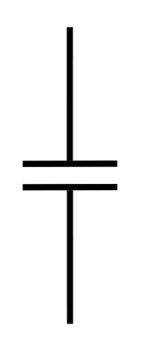
In a electrical circuit diagram a capacitor will have the symbol shown below.
Picture: Capacitor Circuit Component Symbol
A great analogy for how it works is an idealistic water flow in a pipe:
- See this Video: Capacitors Explained – The Engineering Mindset – Paul Evans
- A pipe with a shutoff valve on it will deliver water (or not if valve is closed) instantaneously.
- Now connect the pipe to a large surge or holding vessel and connect another outlet pipe with its own shutoff valve to the bottom of the vessel.
- Starting with both valves closed, open the first value and fill up the surge vessel. Then open the second value to allow flow out.
- Shutting the water inlet valve but keeping the outlet valve open means water keeps flowing until the vessel empties.
- This surge capacity concept is what a capacitor does where the surge capacity is electricity and not water.
A Capacitor consists of two conductive plates separated by a special kind of non-conductive material which we’ll describe later.
Capacitors on a circuit board in an electronic device might appear in a cylindrical shape.
- The cylindrical shape consists of rolled up layers of plates and insulating material.
- This results in a larger surface area in a compact form.
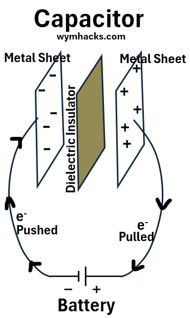
Picture: Capacitor
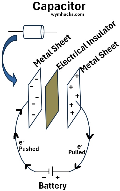
As shown in the drawing above, a voltage source (battery in this example) acts as an electron pump when it is connected to two metal sheets.
- The battery will pull electrons away from the positively connected sheet
- and push electrons onto the other sheet (connected to the negative battery terminal).
Eventually (at equilibrium we can say),
- the metal sheets will store equal amounts of positive and negative charge Q.
- the voltage V across the metal plates will equal the voltage V of the battery
Discharging of a Capacitor
Starting with the simple circuit shown above; once the plates are charged up, what happens if we switch out the battery with a light bulb?
The bulb will light up and then begin to dim until it goes back out signifying that the plates have fully discharged.
So the capacitor can store electrical charges (energy) which can then be used to light up a lightbulb or other types of electrical user (load).
Capacitance
The capacitance of a capacitor indicates its ability to store an electric charge.
Capacitance = how much charge (Q) can be stored for a given voltage (V) across the plates of the capacitor.
C=Q/V ; Capacitor Equation
Where,
- C = capacitance, in units of Farads (F) = Coulombs/Volt.
- Q = charge stored, in units of Coulombs (C).
- Q is the magnitude of the charge on one side of the capacitor
- V = voltage (potential difference) across the capacitor, in units of Volts (V).
Refer to my blog post Capacitance for a detailed derivation.
Be careful how you interpret this equation.
Like R in Ohm’s law, C is considered a constant for a given capacitor because its value is primarily determined by
- its physical characteristics and
- the properties of the insulating material
So, changing Q means that V will change for example, to maintain the same ratio C.
Capacitors and capacitance – Khanacademy – David Santo Pietro
Differential Form of the Capacitance Equation
We know that capacitance = C = Q/V.
We also know that current I is defined as dQ/dt
- i.e. current is the amount of charge passing through a boundary in a fixed amount of time
Rearranging the expression for C we get
Q = CV
Differentiate this expression with respect to time:
dQ/dt = d/dt(CV) =
dQ/dt = current = I = CdV/dt ; Differential Form of the Capacitor Equation
Other Key Equations for Ideal Parallel Plate Capacitor
Refer to my blog post Capacitance for more details on the following equations:
Voltage = Joules/Coulomb = Work/Charge = (E)(d); Parallel Plate Capacitor
Q/V = C = A/(4kπd) ;Parallel Plate Capacitor
Q/V = C = (Aεo)/d ;Parallel Plate Capacitor
Where
- A = Area of each plate.
- d = distance between plates.
- εo = 1/[4kπ]
- k = 1/(4πε0) = coulomb’s constant
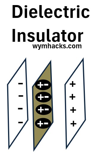
Dielectric Insulator
The material used to separate the charge carrying plates in a capacitor is a special type of insulator called a dielectric.
A dielectric when placed in between the metal does two things.
- It prevents metal from touching it and
- increases the Capacitance.
This is due to the fact that a dielectric has the capacity to be polarized.
A dielectric material has atoms that will be attracted to the charges on the plates. These polarized atoms will
- align themselves such that their negative charges will move towards the plate positive charges and vice versa.
- not move onto the plates because the material is also a non conductor.
- partially offset the charges on the plates.
Scenario 1
- Hook up a battery to capacitor plates (w/o a dielectric) separated by air.
- Fully charge the plates then disconnect the battery.
- Charges and Voltage will remain the same.
- Put a dielectric non conductor between the plates.
- Due to the partial charge offsetting nature of the polarized atom of the dielectric,
- the voltage across the plates will drop
But the total charge is constant.
So, Capacitance = Q/V will increase since Q is constant but V has dropped
Scenario 2
Do the same experiment as above , but keep the battery connected.
- The battery will maintain the voltage by increase the charges on the plates
So, Capacitance = Q/V will increase since V is constant but Q has increased.
Energy Stored in a Capacitor
In the picture below, a capacitor is being charged up by a battery.
Picture: Capacitor Charging
The energy stored in the capacitor can be computed because it must equal the work done by the battery.
The work done by the battery to charge the plates is the change in potential energy when a charge is moved across a potential difference.
Work is (force)(distance) which in electrical terms is (Voltage)(Charge) = (Joules/Coulomb)(Coulomb) = Joules = Energy Units = Work Units
U = Work = Potential Energy = qV
For more on potential energy, read my post: Electricity (5/11); Electrostatics, Current, and Voltage
Because the voltage varies with each electron that is “pushed” from the positive side to the negative side, we have to compute the total work be integrating over infinitesimal changes in voltage.
dU = Vdq
Integrate the expression.
U = ∫Vdq
Recall our Capacitance formula: C = Q/V so V = Q/C
Substituting for V in the U expression gives
U = ∫(Q/C)dq
Using the integration power rule and integrating between Q = 0 to Q, we get
U = Q2/(2C); Energy Stored in a Capacitor (in terms of Q, C)
Using the Capacitance equation we can express this in the following two formats as well:
U = CV2/2 ; Energy Stored in a Capacitor (in terms of V, C)
or
U = QV/2 ; Energy Stored in a Capacitor (in terms of Q, V)
Where
- U = Potential Energy of Capacitor
- Q = Capacitor Plate Charge
- C = Capacitance of Capacitor
Energy Density of a Capacitor
Lets take one of our U expressions and convert it into an interesting expression containing the electric field term E.
U = CV2/2 ; Energy Stored in a Capacitor (in terms of V, C)
For ideal parallel plate capacitors (see my post Capacitance for more details)
- V = Ed and
- Q/V = C = (Aεo/d)
Substitute for C and V into the U expression to get:
U = 1/2(εoE2Ad) , and Ad we can represent as the volume of the capacitor Vc
U = 1/2(εoE2Vc)
U/Vc = 1/2(εoE2); Energy density of the electric field within a capacitor
- : The electrostatic potential energy (or simply “energy”) stored in the capacitor, measured in Joules ().
- This energy is stored in the electric field between the capacitor plates.
- : The volume of the space between the capacitor plates where the electric field exists, measured in cubic meters ().
- : The energy density, which is the energy stored per unit volume, measured in Joules per cubic meter ().
- εo: The permittivity of free space (a constant), which is approximately . It represents the ability of a vacuum to permit electric fields.
- : The magnitude of the electric field between the capacitor plates, measured in Volts per meter () or Newtons per Coulomb ()
Capacitor Summary
Capacitors are fundamental electronic components that store electrical energy in an electric field.
Their behavior is described by several key equations that relate charge, voltage, current, and energy.
- When a voltage is applied across the capacitor, an electric field forms between the plates, causing positive charge to accumulate on one plate and negative charge on the other.
- This accumulation of charge represents stored energy.
- The capacitor resists sudden changes in voltage and can discharge this stored energy back into the circuit.
Key Characteristics
- Capacitance (C): Measured in Farads (F), capacitance quantifies how much charge a capacitor can store per unit of voltage.
- It depends on the plate area, the distance between them, and the type of dielectric.
- Capacitors are like tiny, fast-acting batteries, but they store energy electrostatically, not chemically, allowing for quicker charging and discharging.
Common Uses
Capacitors are used in virtually all electronic circuits for:
- Filtering and smoothing: Removing ripples from DC voltage.
- Timing: Creating delays in circuits.
- Coupling/Decoupling: Blocking DC while allowing AC signals to pass.
- Energy storage: Providing bursts of power.
- Tuning: In radio frequency circuits.
Basic Capacitance Relationship
The most fundamental equation defining capacitance relates the charge (Q) stored on a capacitor to the voltage (V) across it and its capacitance (C):
Q = CV; Capacitor Equation
- Q: Charge in Coulombs (C)
- C: Capacitance in Farads (F)
- V: Voltage in Volts (V)
This equation highlights that for a given voltage, a larger capacitance means more charge can be stored.
Conversely, for a given amount of charge, a larger capacitance results in a smaller voltage across the capacitor.
Capacitance can also be expressed in differential form:
I = Current =dQ/dt = CdV/dt; Differential Form of the Capacitor Equation
Refer to my blog post Capacitance for more details.
Excellent Video References:
- Dielectrics in capacitors – Khanacademy – David Santo Pietro
- Energy of a capacitor – Khanacademy – David Santo Pietro
- Energy stored in capacitor derivation (why it’s not QV)
- Capacitors in series – Khanacademy – David Santo Pietro
- Capacitors in parallel – Khanacademy – David Santo Pietro
- Capacitance – Khanacademy – Sal Khan
Capacitors in Series and Parallel Circuits
Capacitors in series
Capacitors connected in series are arranged end-to-end in a single path, sharing the same charge () but dividing the total voltage () of the circuit across them.
Picture: Capacitors in Series
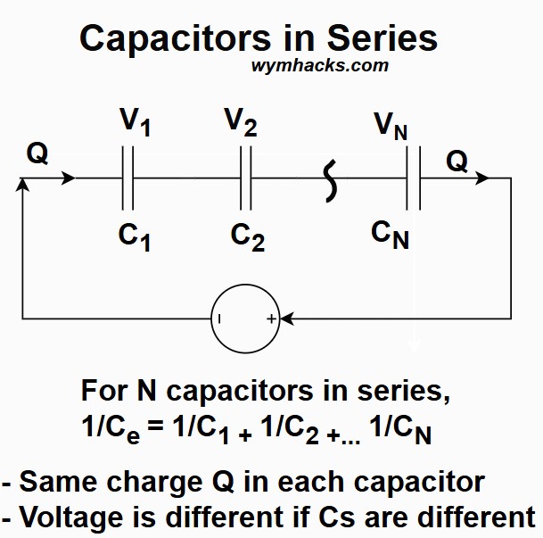
- Charge (Q) is the same: Same charge is stored on each capacitor:
- Qtotal = Q1 = Q2 = Q3
- Voltage (V) adds up
- Voltage is divided across each capacitor based on its capacitance (using V = Q/C)
- Vtotal=V1+V2+V3+
- Voltage drops are different if capacitances are different; V1 ≠ V2 if C1 ≠ C2
- The smallest capacitor has the largest voltage drop.
Equivalent Capacitance (Ce) is a Reciprocal sum.
Ce is always less than the smallest individual capacitor. 1/Ce=1/C1+1/C2+1/C3+…
For N Capacitors in Series: 1/Ce = 1/C1 + 1/C2…+1/CN
For 2 Capacitors in Series: Ce = (C1)(C2)/(C1 + C2)
Parallel Capacitors
Connecting capacitors in parallel increases the total capacitance of the circuit.
In this configuration, all capacitors are connected directly across the voltage source, meaning the voltage () is the same across every capacitor.
Picture: Capacitors in Parallel
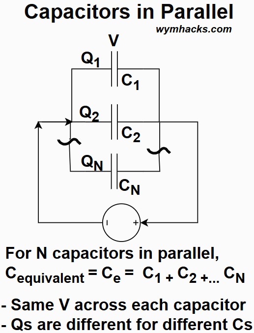
- Voltage (): The potential difference across each capacitor is identical and equal to the total circuit voltage.
- Charge (): The total charge stored is the sum of the charge stored on each individual capacitor.
- Each capacitor stores a charge proportional to its own capacitance, given by .
- Equivalent Capacitance (): The total capacitance is the sum of the individual capacitances.
- This is analogous to how resistors add in a series circuit.
- C=C+C+C+⋯+C
- The equivalent capacitance is always greater than the capacitance of the largest individual capacitor.
- This is because connecting them in parallel effectively increases the total plate area
For N Capacitors in Parallel: Ce = C1 + C2…+ CN
Inductors and Inductance (V = LdI/dt = Ldi/dt)
- note 1: This section is based on the excellent Khanacademy videos that I list at the end of this section.
- note 2: I’ve mostly used the lower case i for current in this section. It could have been written with the uppercase I as well.
Inductor
Picture: Inductor Circuit Symbol
Self Inductance
Consider the following simple circuit.
Picture: Simple Circuit with Inductor (Coil)
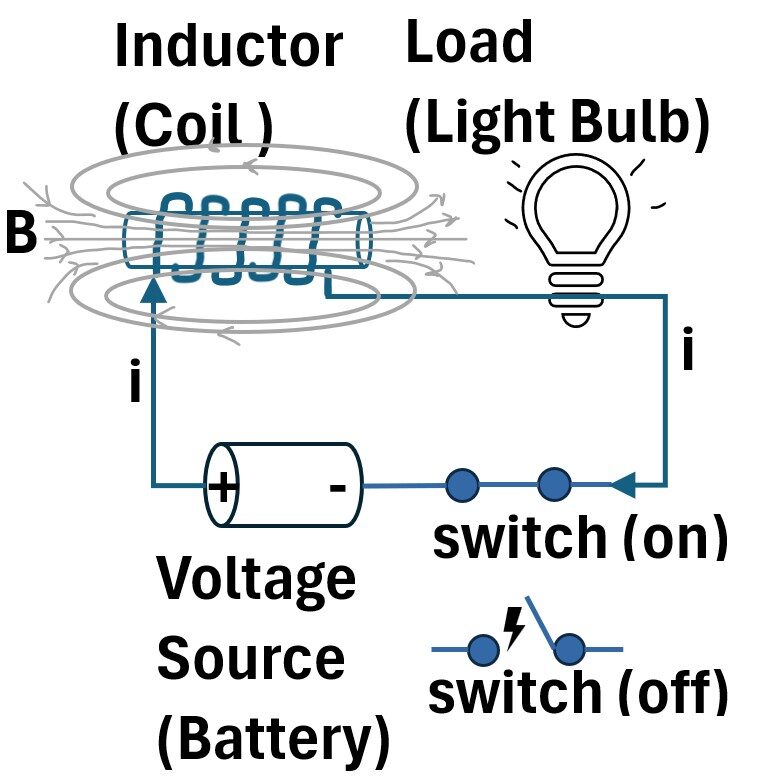
The circuit contains a coil wound around a core of iron which we can call an inductor element (we could call it a Solenoid as well).
When the switch is closed in this circuit, current flows and a magnetic field is generated.
The bulb will take a little time to reach full brightness.
When it reaches maximum brightness, we can use Ohms Law to define the Voltage, Current, Resistance relationship (V = iR = IR).
When the switch is closed making the circuit above “live”, the following occurs:
- The current starts increasing, Δi,
- the magnetic field B in the coil starts increasing ,ΔB (by Ampère’s Circuital Law) ,
- and so does the magnetic flux ΦB in the coil, ΔΦB
Faraday’s law tells us what is happening in the coil (we’ll write it in differential notation indicating an instantaneous infinitesimal change):
t
An EMF is induced , and ,according to Lenz’s Law, it opposes the current.
For a coil or conductor the magnetic flux is proportional to the current,
∝ i
Lets equate them through a proportionality constant L (and we’ll call it the Self Inductance).
= Li (we’ll look at this again in equation (3) below)
Rearrange Faraday’s Law Equation (1) and substitute for
t
EMF = -Ldi/dt
So for an inductor or Coil
t = -Ldi/dt = Faraday’s Law Applied to an Inductor (coil)
Self-inductance (L) is the property of an electric circuit (like a coil) that opposes any change in the electric current flowing through it.
It is expressed as the proportionality constant L equating the rate of change of current with time to the change of flux with time.
L, self inductance,
- has units of volt-seconds/amp = Vs/A (called a Henry).
- only depends on the geometry and material used and
- just like capacitance and resistance, it does not depend on i or V.
When the switch in a circuit with an inductor is suddenly opened,
- the current attempts to drop instantaneously.
- As the current rapidly drops, the inductor coil, obeying Lenz’s Law, opposes this with an increase in EMF with enough energy to jump the air gap in the open switch (you get a spark).
- The spark is a result of the inductor’s stored energy rapidly discharging across the gap in a final attempt to keep the current flowing
Self Inductance in a Solenoid
The inducting coil we described above is called a solenoid.
It is a device composed of a helix (a coil of wire) that, when an electric current passes through it, generates a uniform magnetic field inside the coil.
= Li to derive t = -Ldi/dt.
Let’s take a closer look at it.
= Li ; Flux Linkage
- where Nis described as the “flux linkage”.
- This equation is analogous to the momentum equation: ρ (momentum) = (inertia or mass)(velocity)
- Just like mass is a body’s resistance to a change in its velocity (its inertia),
- a coil’s inductance ,L , is an electrical inertia, resisting changes in the current through it.
- Momentum is a measure of the “quantity of motion” stored in an object while the
- flux linkage () is a measure of the magnetic “inertia” stored in the inductor’s magnetic field.
Just as a moving object carries momentum proportional to its mass and velocity, an inductor carries a magnetic quantity (flux linkage) proportional to its inductance and the current flowing through it.
Rearranging (3), we get
(4) L = /i
We have an expression for the magnetic flux:
(5) ΦB = Magnetic Flux = (B)(Ap) =BAcos(θ) = B̄•Ā for a Uniform B and Flat Surface
Picture: Single Coil of a Solenoid
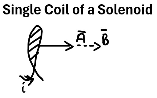
In the case of a solenoid coil, θ = 0 . cos(0) = 1, so,
(6) ΦB = BA
Substituting (6) into (4) we get:
(7) L = BA/i
We want find an expression for B and substitute it into (7).
Let’s use the expression relating i to B called Ampère’s Circuital Law:
(8) ∮B̄•dL̄ = μ0ienc ; Ampere’s Circuital Law
It states that the Path integral of B̄⋅dL̄ on a closed curve (the Amperian Loop) is equal to μ0 times the net enclosed current passing through a surface defined by the curve.
- ∮ is a closed line integral.
- i.e. summing up the contributions of the magnetic field along a complete, closed path, known as an Amperian loop.
- The integral path starts and ends at the same point.
- B̄ = Magnetic Field
- This is the magnetic field vector.
- B represents the magnitude and direction of the magnetic field at every point along the Amperian loop.
- Its SI unit is the tesla (T).
- dL̄ = Infinitesimal Line Element
- This is a small, infinitesimal vector segment of the closed loop.
- It points in the direction of the integration along the loop.
- Its SI unit is the meter (m).
- The dot product B̄•dL̄ calculates the component of the magnetic field that is parallel to the path element.
- ∮B̄•dL̄ ; This term is called the circulation of the magnetic field.
μ0 = Permeability of Free Space.
- A constant that represents the ability of a vacuum to support the formation of a magnetic field.
- Its value is approximately 4π×10 −7 T⋅m/A.
- ienc = Enclosed Current:
- This is the net electric current that passes through the surface defined by the closed Amperian loop.
- It is a scalar quantity, and its SI unit is the ampere (A).
We can simplify the left hand side of (8) by assuming we have a constant B field in the middle of the coil.
We can draw a hypothetical closed Amperian Loop as shown in the picture below.
Picture: Solenoid Inductor With Amperian Loop
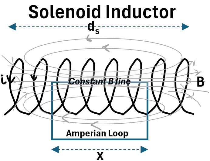
The only component of ∮B̄•dL̄ that is non zero in the Amperian Loop is the side of the rectangle aligned with the constant (straight) B field.
So equation (8) simplifies to
(9) Bx = μ0ienc
ienc can be expressed as Nenci :
(10) Bx = μ0Nenci
But Nenc = N(x/ds). Substituting for Nenc into (10) gives us
Bx = μ0N(x/ds)i which simplifies to
(11) B = μ0Ni/ds ; Magnetic Field Magnitude in a Solenoid
Substitute (11) into equation (7) to get
(12) L =
where
- L = Self Inductance
- N = number of loops in the coil
- μ0= a constant; the Permeability of Free Space (for air or vacuum)
- A = bounded area of each loop
= length of the solenoid coil
If we wrap the coil around a ferromagnetic rod or core, we can achieve a much higher inductance.
We can modify equation (12) to reflect this by defining a total permeability term:
- The total permeability ( of any material is defined as the product of the permeability of free space and the relative permeability of that specific material
- =
- For air/vacuum: ≈1
- For ferromagnetic cores: can be very large (e.g., 5,000 for soft iron).
So Equation (12) becomes,
(13) L =
- μr = a constant; the Permeability of the core (ferromagnetic material).
- μ0 = a constant; the Permeability of Free Space (for air or vacuum)
Energy Stored in an Inductor
If we take our simple circuit and bypass the battery we’ll effectively have a short circuit.
Picture: Circuit with Inductor: Short Circuit
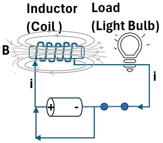
The bulb will eventually go out but it will do it progressively.
This happens because inductors will resist changes in current.
Since di/dt is decreasing, then the induced EMF is increasing, meaning the resultant induced voltage will induce the current to continue.
So the inductor is actually providing energy to the bulb in this scenario.
Energy balance around the bulb
Let’s do an energy balance around the load (the bulb).
- We will develop the balance in terms of energy per time, or Power.
- From Ohm’s Law and Joule’s Law we know that power = (current)(voltage) = P = IV = iV
- Total Energy generated in the Inductor = Energy Transferred to Bulb
- U=Total energy per unit time = Vi = (-Ldi/dt)i ; where units of measure are energy/second (units of power):
- = (ampere)(joules)/[(ampere)(second)]
- = (ampere)(joules)/(coulomb)
- = (current)(voltage) = iV
If the power was constant we could just multiply by the total time to get the total energy, but power is not constant.
This is why we integrate.
Integration, at its core, is a process of summing an infinite number of infinitesimal parts.
It allows us to calculate a total value for a property that is changing at every single point.
dU/dt = (-Ldi/dt)i
dU = (-L)(i)(di)
U= ∫(-L)(i)(di) = -Li/2 evaluated from i = I to 0 (note: we integrated using the power rule where ∫idi = i/2)
(14) U= LI/2 ; magnetic potential energy stored in an inductor
An inductor (like a coil of wire) stores energy in the magnetic field created by the current flowing through it, and this formula calculates that stored energy.
- U= Energy (Magnetic Potential Energy) in Joules (J) = the total amount of energy stored in the inductor’s magnetic field.
- L = Inductance in Henrys (H) = A measure of an inductor’s ability to resist changes in electric current by inducing an opposing voltage (back-EMF).
- It’s a property determined by the coil’s physical characteristics (number of turns, area, length, and core material).
- Current in Amperes (A) = the instantaneous current flowing through the inductor.
Similarities to Energy in a Capacitor
In the section on capacitance we showed that the potential energy stored in a capacitor is
U= CV2/2 ; Energy Stored in a Capacitor (in terms of V, C)
which is analogous to the Magnetic potential energy stored in an inductor
- Electric Field ()
- (Capacitor)
- Energy density in Joules/m3: u
- Be careful to remember that V is voltage but Vc is volume
- Magnetic Field ():
- (Inductor);
- Energy density in Joules/m3: u
Notice that the energy density terms do not contain C or V or L or I.
In fact, the energy density equations are completely general, even though they were derived using a capacitor model and an inductor model.
The energy density equations derived from capacitors and inductors are general because
- they represent the fundamental principle that energy resides in the electromagnetic fields themselves,
- and not in the physical components.
Here we’ll develop some equations based on a simple model where we are connecting alternating AC current to a coil.
In the picture below, imagine that the two coils below are the primary and secondary coils of the residential transformer providing power to your house. (or you can simulate that with two coils where one coil is plugged into your outlet).
Picture: Two Coils: One Connected to AC with Second connected to Bulb
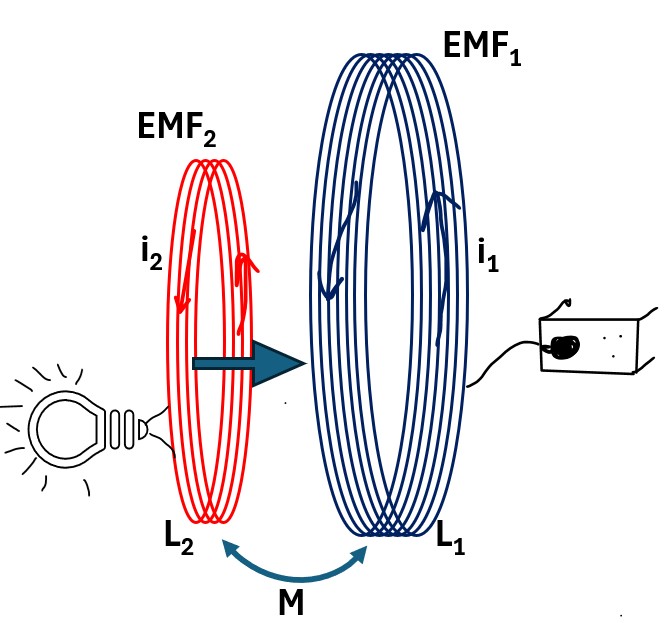
From the AC outlet,
- an alternating current iis generated in the primary coil , which
- induces a changing magnetic field B in the primary coil (by Ampere’s Law)
- which cut’s over into coil 2 (secondary coil)
- which generates an EMF (voltage) in coil 2 (EMF)
- which generates an alternating current iin coil 2 (by Faraday’s Law)
- which lights the bulb.
- The Induced Voltage in the secondary coil. This is the energy transferred from the primary to the secondary circuit.
- Rate of change of current in the primary coil.
- Since AC (alternating) current is constantly changing, this term is non-zero.
- The faster the primary current changes, the larger the induced EMF will be.
- = The Coupling Coefficient = Mutual Inductance
- This is a constant of proportionality that describes the magnetic coupling between the two coils.
- It tells you how effective the primary coil’s magnetic field is at linking with the secondary coil.
depends on:
- The number of turns in each coil ( and ).
- The size and shape of the coils.
- The distance and orientation between the coils (proximity).
- The magnetic material (like an iron core, or just air) linking the coils.
- The Negative Sign (Lenz’s Law)
- The induced EMF () will always create a current that produces a magnetic field opposing the change in flux that caused it (
Total EMF Equations for Two Coils
From our two coil analysis above we noted that “The coil 2 current iwill also create its own magnetic field Bwhich also cuts over into coil 1.”
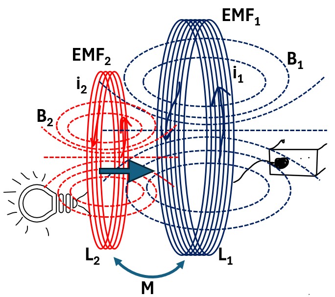
The Total induced EMF in each coil is therefore a summation of contributions from both self inductance and mutual inductance.
(22a) EMF = -Ldi/dt – Mdi/dt = -Ldi/dt – Mdi/dt ; Total induced EMF in primary coil of a coupled coil system (transformer)
(22b) EMF = -Ldi/dt – Mdi/dt = -Ldi/dt – Mdi/dt ; Total induced EMF in secondary of a coupled coil system (transformer)
where
- M= Mutual Inductance of coil 1 with respect to coil 2
- M= Mutual Inductance of coil 2 with respect to coil 1
- It turns out that M will always equal M so we can express it as M.
- the sign convention for the M terms will depend on the the construction of the coils (the side of the coil in which the winding starts and the direction of the coil winding)
- LL= Self Inductance of coil 1 and 2 respectively.
Finally,
Please note that we are only talking about induced EMF in the equations above.
But the the first coil in our setup also has an EMF voltage provided by the Alternating Current power supply.
If you were to do a voltage balance in this circuit , you would also have to include the voltage provided by the power source which can be expressed using Ohms Law (V = IR).
Mutual Inductance Expressed Via Self Inductances
Consider our two coil model from the previous section.
We know from equation (4) that the self inductance for each coil will be
(4a) L = /i
(4b) L = /i
And from equation (18)
(18a) M = NΦB12/i
(18b) M = NΦB21/i
Where ,you will recall, the two subscripts a and b in ΦBab mean
- a is the destination, where the magnetic flux is being linked to or being cut over to
- b is the magnetic flux source
We also know that M = M= M
so we can equate equations 18a and 18b.
(23) M = NΦB12/i= NΦB21/i
In reality, some magnetic flux “leaks” and doesn’t reach the other coil.
We account for this with the coupling coefficient (k), which ranges from 0 to 1.
(24) ΦB12 = kΦB2
(25) ΦB21 = kΦB1
Substitute equations 24 and 25 into equation 23.
(26) M = NkΦB2/i = NkΦB1/i
Express equation 26 as the square of M.
(27) M x M = M = (NkΦB2/i)( NkΦB1/i )
Express equation 27 in terms of the self inductances via equations 4a and 4b.
(28) M x M = M = (kL)( kL )
(29) M = k√(LL) ; Mutual Inductance (M) between two coils
Equation 29 defines the Mutual Inductance (M) between two coils based on their
- individual self-inductances (L1 and L2) and
- how well they are magnetically linked.
The Coupling Coefficient (k): This is a value between 0 and 1 that represents the efficiency of the magnetic connection.
- If k=1, the coils are “perfectly coupled” (all magnetic flux from one hits the other);
- if k=0, they are completely isolated.
The term √(LL): represents the theoretical maximum mutual inductance possible for those two specific coils.
Practical Meaning: In the real world, M is always less than or equal to this geometric mean because some magnetic flux “leaks” into the surrounding air rather than passing through the second coil.
Watch these excellent Khanacademy Videos
Inductors in Series and Parallel Circuits
Inductors in series
An inductor resists an instantaneous change in current.
Inductors in a series circuit are connected end-to-end, creating a single path for the current.
This configuration increases the total opposition to changes (inductance) in current.
Picture: Inductors in Series
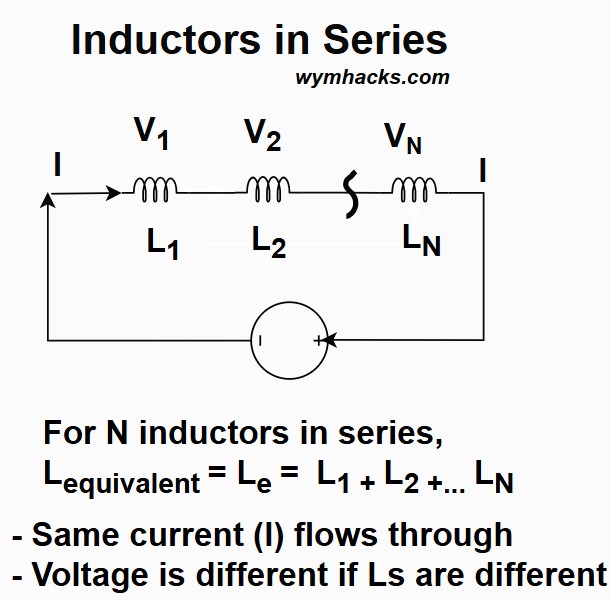
- In a series circuit, the current is the same at every point. This applies to inductors in series as well:
- A key characteristic of all inductors, regardless of connection, is that the current through an inductor cannot change instantaneously.
- The back electromotive force (EMF) generated by the changing magnetic field opposes the change in current, forcing the current to rise or fall gradually (transient response).
- The total voltage across the series combination is the sum of the individual voltage drops across each inductor, according to Kirchhoff’s Voltage Law (KVL):
- + …
- The voltage across a single inductor is proportional to the rate of change of current ()
- V=Ldi/dt (see the inductance section)
- The rate of change of current () is the same for all series inductors, so, the voltage drop across each inductor is proportional to its own inductance value ().
- Unlike a capacitor, an inductor does not store charge. Instead, an inductor stores energy in its magnetic field. This stored energy is given by:
- (see the inductance section)
- In a series circuit, each inductor contributes to the total stored energy.
- The larger the total series inductance, the more energy the entire combination can store for a given current ().
- Total Inductance: The equivalent inductance () is the sum of the individual inductances, similar to resistors in series.
- For inductors connected in series with no mutual coupling between them:
For N Inductors in Series:
Inductors in Parallel
In a parallel inductor circuit, the behavior of voltage, current, and charge follows specific rules.
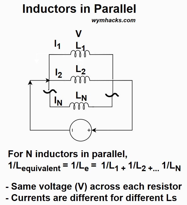
- Voltage
- The voltage is the same across all inductors connected in parallel. This is a fundamental property of all parallel circuits.
- …
The total current flowing into the parallel combination divides among the individual inductors, following Kirchhoff’s Current Law (KCL):
+ …
Relationship to Inductance: The current division is governed by the individual inductances.
- For ideal inductors, the total current’s rate of change () is related to the voltage across them ().
- Since the voltage is the same, the branch with the smaller inductance () will have a larger rate of change of current ().
- Over time, the current through the inductors is inversely proportional to their inductance:
- Inductors store energy in a magnetic field created by the current flowing through it.
- Energy Storage: The total energy (E) stored in the parallel combination is the sum of the energy stored in each individual inductor, which is related to the current through it and its inductance:
- + …
- (see the inductance section)
- The process of the current increasing and the magnetic field building up is analogous to “charging” a capacitor, where a higher current over time corresponds to a higher energy level in the magnetic field.
- Connecting inductors in parallel decreases the overall or equivalent inductance () of the circuit.
- The formula for the equivalent inductance (assuming no mutual inductance) is the same as for parallel resistors:
For N Inductors in Parallel: 1/L = 1/L + 1/L +… + 1/L
Summary: i-v (I-V) Equations for Ideal Circuit Elements
Resistor
Picture: Resistor Element Convention
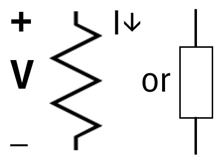
-
iv = IV Equation: v=iR = V = IR ; Resistor Equation
- v: voltage (V = voltage)
- i: current (A = amperes)
- R: resistance (Ω = ohms)
- Physical Meaning: Dissipation: Energy is lost as heat. Voltage is directly proportional to the current flowing through it at that exact moment.
Capacitor
Picture: Capacitor Element Convention
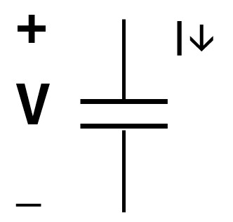
-
iv = IV Equation: i(t)=Cdv/dt = CdV/dt ; Capacitor Equation
- C: capacitance (F = Farad)
- dv/dt = dV/dt: rate of change of voltage
- Physical Meaning: Storage (Electric Field): Current only flows when voltage is changing. It resists sudden changes in voltage.
Inductor
Picture: Inductor Element Convention
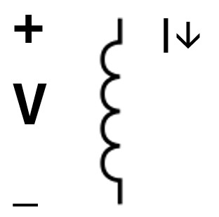
-
iv = IV Equation: v=Ldi/dt = V = LdI/dt ; Inductor Equation
- L: inductance (H = Henry)
- di/dt = dI/dt: rate of change of current
- Physical Meaning: Storage (Magnetic Field): Voltage is produced only when current is changing. It resists sudden changes in current.
Variable Descriptions
- Voltage (v = V): The electrical potential difference (the “pressure”) between two points.
- Current (i = I): The flow of electric charge (the “flow rate”) through the component.
- Resistance (R): The measure of opposition to current flow.
- Capacitance (C): The ability of a component to store charge per unit of voltage.
- Inductance (L): The property of a conductor by which a change in current induces an electromotive force.
Frequency’s Impact on Circuit Elements
In electrical engineering, voltage and current are measured over time as sinusoidal waves.
See my post for more on this:
Because these signals oscillate, they possess a frequency characteristic—a measure of how many cycles occur per second, expressed in Hertz (Hz).
The frequency indicates how quickly a wave goes through one cycle (high frequency will show as more peaks and troughs in a given time period).
- Low Frequency: The signal oscillates slowly over time.
- High Frequency: The signal oscillates rapidly, flipping direction thousands or millions of times per second.
The “impact” of frequency refers to how resistors, capacitors , and inductors react to the speed of these oscillations.
This behavior is rooted in the calculus of their fundamental equations and is quantified by Reactance (X).
Reactance is the opposition that inductors and capacitors offer to alternating current (AC) by storing and releasing energy in magnetic or electric fields, rather than burning it off as heat.
The Resistor: The Frequency-Independent Element
The resistor equation (Ohm’s Law: V = IR) has no derivative component (no d/dt).
So, the resistor doesn’t care how fast the sine wave is flipping.
Whether the frequency is 1 Hz or 1 GHz, the opposition remains constant.
It has no “reactance,” only resistance.
Frequency Impact: None. The resistance remains constant regardless of signal speed.
The Capacitor: Passes High Frequency, Blocks Low Frequency
A capacitor stores energy in an electric field. Its time-domain behavior is defined by:
The current (I) is directly proportional to the rate of change of voltage (dV/dt) over time.
In a high-frequency sinusoidal signal,
- the voltage changes incredibly fast (the slope of the wave is steep),
- making the derivative a very large number.
- This results in high current flow.
To calculate this opposition in Ohms, we use Capacitive Reactance (XC):
XC = 1/(2π f C); Capacitive Reactance
- At High Frequency: As f gets larger, XC drops toward zero. The capacitor allows the signal to zip through, acting as a Short Circuit.
- At Low Frequency (DC): At 0 Hz, there is no change over time (dV/dt = 0). XC becomes infinitely large, acting as an Open Circuit.
The Inductor: Passes Low Frequency, Blocks High Frequency
An inductor stores energy in a magnetic field and is defined by:
- An inductor acts like “electrical inertia.”
- If a sinusoidal signal tries to change the current direction rapidly (High Frequency),
- the derivative becomes huge, and
- the inductor generates a massive “back-voltage” to fight that change.
Its opposition in Ohms is called Inductive Reactance (XL):
XL = 2πfL ; Inductive Reactance
- At High Frequency: As f increases, XL grows. The inductor fights the rapid flipping of current, acting as an Open Circuit.
- At Low Frequency (DC): At 0 Hz, the current is steady over time (dI/dt = 0), so the inductor produces no opposing voltage. It acts as a Short Circuit.