Menu (linked Index)
Refractive Geometric Optics
Last Update: December 26, 2024
Introduction
Geometric Optics (AKA Ray Optics) studies the behavior of light in terms of rays.
It treats light as straight lines traveling in specific directions.
I wrote this article with the intent of describing eye related geometric optics, so the focus is on refraction (bending of light) through media and not reflection.
The material is organized into the following ideas / concepts:
- Ray theory and the Law of Refraction.
- Lenses: Basic Definitions
- Ray Diagrams and Application to Convex and Concave Lenses.
- The Eye acts like a Convex Converging Lens.
- Lens equations (formulas).
References
- Khanacademy.org
- Introduction to Geometric Optics – Openstax – College Physics
- Michel van Biezen Physics Videos
- Paul Andersen bozemanscience.com
References: My Other Related Articles
Find more links related to my eye research here: Understand Your Eyes.
Here is a list of other articles I’ve written that are referenced in this article.
Optics Defined
Optics is a branch of physics that studies the properties of light and its interactions with various materials.
Light is electromagnetic radiation.
The human visible spectrum of light represents a small section of the full range of light which is called the Electro-Magnetic Spectrum (EMS).
- The EMS, in-total, can be described as Electro-Magnetic Radiation (EMR).
- Visible light represents only a small portion of the full EMS
- Visible light ranges from roughly 400 nanometers, nm, of wavelength (UV light) to about 750 nm (Infrared light).
The study of light gets quite complicated.
- On a “macro” level (i.e. when we see things with our eyes or with basic instruments), light is modelled as a ray travelling in a straight line, sort of like a discrete point or particle would travel.
- On a much smaller or “micro” level, light is typically modelled as a wave with wave properties like wavelength (distance between peaks or troughs) and frequency (number of waves that pass a fixed point in a certain period of time)
- Quantum Mechanics is the Physics field that explains the relationship between this particle-wave duality.
- Probably some of the smartest scientists work (or have worked) in this arena.
Why don’t you jump to this post now and get a quick “light” refresher.
In this article, we’ll study light (mainly) as a straight moving ray and how the ray interacts with different media (e.g. air, solids, and liquids).
This area of study is called Geometric Optics.
Ray Theory
Geometric Optics makes the following assumptions regarding Light Rays:
- Light can come directly from a source through empty space (from the sun) or otherwise (Light from a light bulb through air).
- Incoming light (Incident Light) can be absorbed, reflected, or transmitted.
Picture_When Light Moves from One Medium to Another
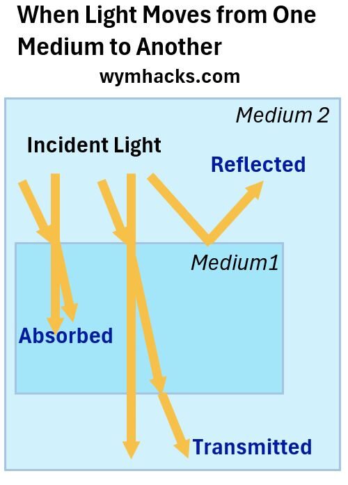
Note: Absorption and Reflection are nicely described by a green leaf where all the colors have been absorbed except for Green Light. You can read my blog on color for more on light and color perception.
- Light can travel (transmit) through various media (e.g. air,glass,your eyeballs, etc.)
- Light travels in straight lines called Rays.
- The Rays may change direction when reflected/absorbed/transmitted, but will then resume going in a straight line.
- Geometry and Trigonometry are used to quantify the behavior of light.
We’ re interested in the transmittance of light in this article.
What Happens To Light Travelling in a Refractive Medium?
Consider the drawing below where light enters perpendicularly through the surface (i.e. at 90 degrees) or at another angle to the surface of a “transparent” medium like glass or water.
Picture_Light Travelling Through A Refractive Medium Will Slow
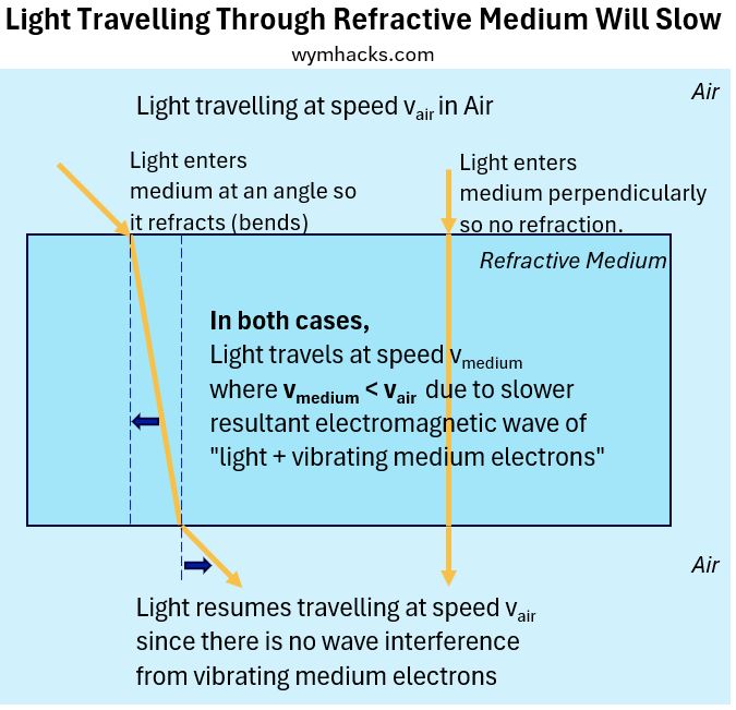
This light will have the following characteristics:
- Regarding the light coming in at an angle (the left ray in the diagram):
- The incident ray will begin to refract or bend at the boundary between air and the second medium which we assume is glass.
- It will bend towards the normal line (the dotted blue vertical line).
- Once in the medium it will assume a new straight line trajectory
- The light will travel slower than it did in air. The physical properties of the glass cause this to be so (more later).
- When it exits into air, it will once again refract or bend.
- This time it will bend away from the normal line and resume a new straight line trajectory.
- This light will be parallel to the incident ray line but will be offset by some distance that can be calculated.
- Regarding the vertical light entering at 90 degrees to the surface:
- The light will not bend or refract.
- It will still slow down in the glass, and
- it will speed back up as it exits the glass, and
- it will do all of this in a straight line.
Refraction Analogy
The refraction that occurs can be intuitively explained with an analogy of a car, or tank, or marching band entering a rough surface from a smooth surface and then back out to the smooth surface:
- Using a tank analogy from the perspective of the tank driver,
- the right tread slows down upon entry into the rough surface, causing the tank to veer right (towards the normal line).
- Upon exit from the rough surface, the right tread now speeds up first and the tank veers to the left (away form the normal line).
- See more details of the tank analogy here.
Let’s next talk about the simple, elegant equation that defines this behaviour.
The Law of Refraction
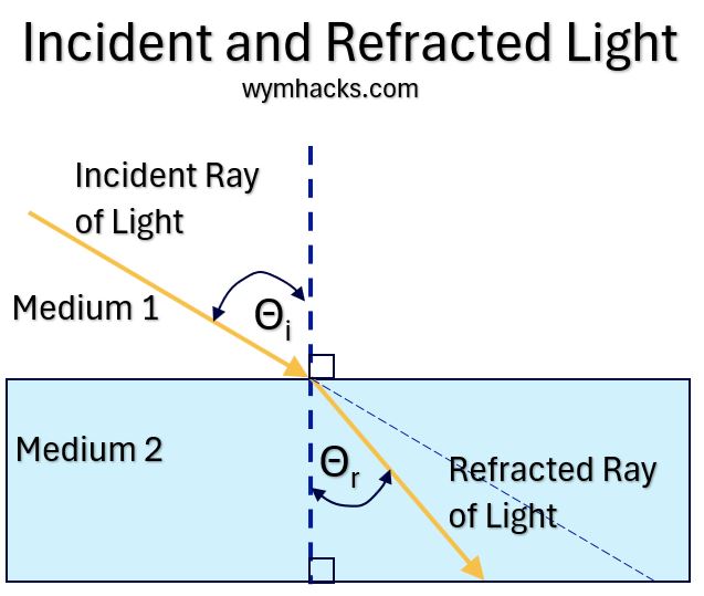
See the picture below.
Consider an Incident Light Ray travelling in Medium 1 which enters the boundary of Medium 2 at an angle.
The resultant Refracted Light Ray is shown in Medium 2
- The Angle of Incidence, θi , is the angle between the Incident Light Ray and the normal (dotted line) to the surface,
- while the Angle of Refraction, θr, is the angle between the Refracted Light Ray and the normal (dotted line) to the surface.
Picture_Incident and Refracted Light
The Law of Refraction states that the ratio of the sine of the Angle of Incidence to the sine of the Angle of Refraction is constant for a given pair of mediums:
Law of Refraction: sin θr / sin θi = constant
Some (most?) of the great scientific theories and laws are usually the result of contributions from many people over many years.
The Law of Refraction is one such law.
History of Snell’s Law
I mainly used the following references to assemble this list:
Here is a bulleted chronological , probably not complete, listing of how the Law of Refraction came to be called Snell’s Law:
- The problem of refraction was known to the Greeks in the first century A (Ptolemy‘s “Optics”).
- Ibn Sahl (940 – 1000 AD), a Baghdadian Arab scholar, accurately stated the Law of Refraction in 984 AD (in his treatise “On Burning Mirrors and Lenses)
- Another influential Baghdadian Arab Scholar, Alhazen (Hasan Ibn al-Haytham 965 – 1040 AD) did extensive work in refraction in his Book of Optics (Kitab al Manazir).
- He was aware of Sahl’s work but did not discuss work on refraction.
- He is often called the “father of modern optics” and influenced some of the great thinkers of the scientific revolution in the 16th and 17 centuries.
- In 1602, Thomas Harriott might have come up with the Law of Refraction. He discussed it with Johannes Kepler.
- The Dutch scientist Willebrord Snellius (1580–1626) derived the equation in 1621, but never published it.
- In his publication “Dioptrics”, the Frenchman René Descartes (1596 – 1650) derived the law.
- Christiaan Huygens, another Dutch scientist, “in his Traité de la Lumière in 1678 derived the law yet again though he acknowledged the prior work of Snellius, permanently cementing the shortened name “Snell” to the law of refraction.”
- In the 1600s, Fermat , Huygens, and Newton did important work in developing theories regarding refractive properties of materials and light.
- In the 1700s, Euler, Klingenstierna, and Dollond’s work on achromatic lenses encouraged further work to understand refractive properties of materials
- Thomas Young in 1807 came up with the concept of the refractive index as we know it today.
So, today, we call the Law of Refraction Snell’s Law.
But it was in the 1800s in which the modern form of the equation was established.
Modern Version of Snell’s Law
Recall that Snell’s Law as originally expressed is: sin θr / sin θi = constant
The modern version of Snell’s Law breaks down the constant expression into more meaningful terms.
Picture_Snell’s Law
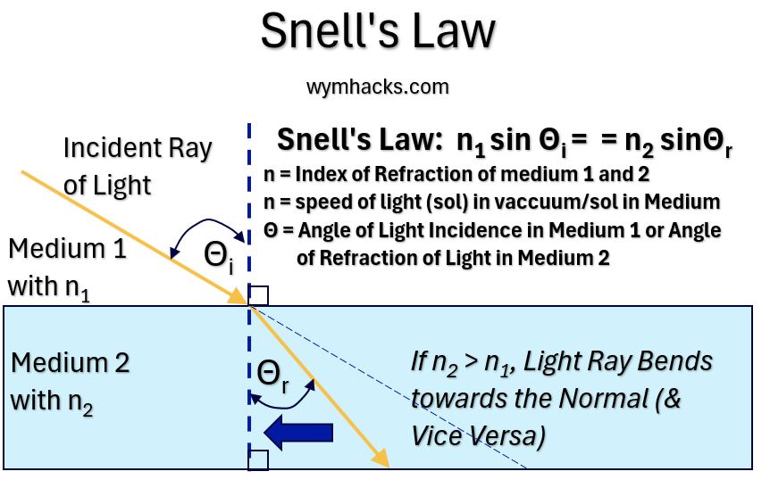
In the modern version of Snell’s Law, the constant is expressed as n1/n2 where n is the Index of Refraction for each Medium.
We can now write Snell’s Law as:
Snell’s Law: n2 sin θr = n1 sin θi
The Index of Refraction n for each medium is defined as: (speed of light in a vacuum)/(speed of light in the medium);
- n = c/v
If we substitute this expression into Snell’s equation we get:
- c/v2 sin θr = c/v1 sin θi
- v1 sin θr = v2 sin θi
Snell’s Law Observations
Go to here to see an example of Snell’s Law worked out for light passing from air to water and back out to air.
Snell’s law shows that:
- Light travelling into a optically more dense material (i.e. higher Refractive Index) will refract (bend) “towards the normal”.
- Light travelling into a lower Refractive Index material will refract “away from the normal”
To determine the angle of reflection of light into your retina you could apply Snell’s equation at each of the medium boundaries.
Picture_Eye Medium Boundaries and Refractive Indices
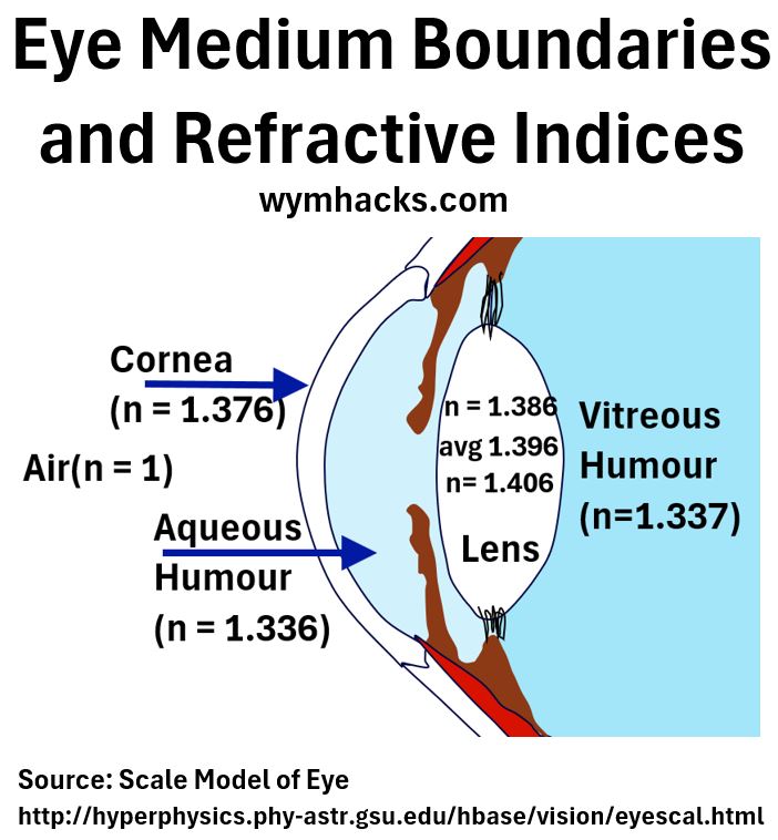
In this case there are (at least) four boundaries depending how detailed you want to get):
- Air/Cornea; n = 1 & 1.376 respectively
- Cornea/Aqueous Humor; n = 1.376 & 1.336
- Aqueous Humor/Lens; n = 1.336 & 1.396 (avg)
- Lens/Vitreous Humor; n = 1.396 & 1.337
Many of the tools and corrective procedures that Optometrists and Ophthalmologists use are based on Snell’s Law.
Before we jump to learning about lenses, let’s tidy up one lingering question you might have:
How can light just slow down and then speed right back up to its original speed when going into and out of a medium?
Why Does Light Slow Down?
- Incident Light excites the atoms of the refractive material
- The electrons of these atoms begin to oscillate (vibrate) and produce their own electromagnetic waves
- These waves interfere with the light waves and
- produce a resultant wave that travels at a slower speed.
- When Light exits the medium back into the air, interference ends and the light resumes its original speed.
Go to this post for more details to see how the additive nature of waves (superposition) explains this slowing down effect.
Ok, so we now know that we can predict the angle of refraction of incoming light when it enters a refractive medium like glass or water. (We can of course also compute the exit refraction angle as well.)
Next, let’s talk about refractive surfaces that have concave or convex shapes (i.e. lenses).
Lenses
Your sight , of course, consists of images that you “see”.
An image of any object you see is projected onto your Retina where it’s translated into signals that are routed to your brain via the Optic Nerve.
In Geometric Optics, an object that we see is typically represented by an upright arrow (see the drawing below).
The object essentially consists of numerous points of light all of which sum to make up the image you see.
The eye bends or refracts the incoming light rays from any object and routes the resultant image to the Fovea (that is the natural design at least).
Notice that the image on the Retina is inverted but your brain ultimately converts this to the upright image you eventually see.
We learned in a previous section that we can use Snell’s Law (n2 sin θr = n1 sin θi ) , to figure out the amount of bending that occurs.
Picture_The Eye Projects a Real Inverted Image
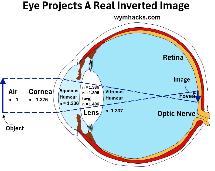
So, you would apply Snell’s law to each of the medium boundary changes of which there are four:
- Air to Cornea,
- Corena to Aqueous Humor,
- Aqueous Humor to Lens, and
- Lens to Vitreous Humor.
Assuming we have
(1) two refraction systems represented by the Cornea and the Lens, (Air/Cornea/Aq.Humor) and (Aq.Humor/Lens/Vit.Humor) and
(2) the Ciliary Bodies are in a relaxed state (i.e. the lens is at its maximum length):
- The Cornea “system” accounts for about 67% of light refraction and the
- Lens “system” accounts for the remainder (about 33%)
- The ability for a lens to refract is described as the Power of the lens.
The eye uses its Cornea and Lens to converge light to form images.
- The Cornea has a convex anterior (front) surface and a concave posterior (back) surface but in total acts as a converging lens (i.e. light refracts inwards).
- The Lens is a biconvex asymmetrical lens that is also a converging lens.
We can understand light convergence and divergence better by studying the Geometric Optics of symmetrical concave and convex lenses.
Symmetrical Concave and Convex Lens
Let’s use symmetrical (both sides are the same) convex and concave lenses to define some key measurements. Refer to the picture below as you read on.
Consider incident light rays hitting a lens surface.
According to Snell’s law, the rays will refract inwards or outwards depending on the angles of incidence and the indices of refraction.
I show the normal lines at a and b in the biconvex lens picture below showing that the light bends towards the normal through the first boundary and then bends away from the normal at the second boundary.
Picture_Biconvex Lense
![]()
Picture_Biconcave Lense
![]()
The Optical Center of a lens is the point where incoming light rays pass through without being refracted.
- In a symmetrical lens the optical center is located at the geometric center of the lens.
- The Principal Axis is the horizontal line passing through the Optical Center.
- In an asymmetrical lens the optical center may not be at the geometric center.
The Focal Point F of a lens is the point where parallel (to the Principal Axis) light rays “converge” after passing through the lens.
- The term Plus or Minus lens is often used in Optics. These indicate whether the power has increased (Plus) or decreased (Minus).
- For Converging Lenses (Convex or Plus Lenses), parallel light rays entering the lens will converge (bend inwards) to a single Focal Point.
- For Diverging Lenses (Concave or Minus Lenses), parallel light rays entering the lens will diverge (bend outwards).
- The Focal Point is traced back from these diverging rays.
- We say here that virtual rays traced back from the diverging rays, converge at the Focal Point.
- The Focal Distance f is the distance from F to the Optical Center.
- For symmetrical lenses , F and f are located on both sides, equidistant from the the Optical Center.
Definition of Power
The Focal Distance f is an indicator of lens Power.
- A shorter focal distance indicates a stronger focusing power.
- Lens Power is defined as 1/f in units of inverse meters or Diopters.
- Example 1: f = 10 cm = .1 m; 1/f = 10 m-1 = 10 Diopters (i.e. Greater Power than Example 2)
- Example 2: f = 20 cm = .2 m; 1/f = 5 m-1 = 5 Diopters (i.e. Less Power than Example 1)
- Using Diopters is useful as it is a direct measurement of Power
- In our example above Eg1 Power = 2 x E2 Power)
- The Power of multiple lens would be the sum of their individual powers.
Ray Diagrams and Rules for Drawing Them
Ray diagrams are essential for understanding how light interacts with lenses and mirrors
They help us understand the location and magnitude of lens images in relation to the location of their objects (the source of light; typically reflected light but could be produced light).
- Using the Principal Axis and the Centerline of a lens as effective x and y cartesian coordinates (i.e. x, y graph axes),
- An Object, the thing seen, is placed “to the left” of a lens.
- The Object is represented by an upright arrow with its base on the principal axis.
- We assume the thickness of the lens is negligible with respect to the length (Thin Lens Assumption)
- We thus draw rays to the centerline of the lens and not to the edges.
- For each point source on this Object, a ray diagram depicts a series of rays that will intersect at an Image point
- The total of all the Image points will represent the full Image of the Object that is projected by the lens.
- Each image point is located using any two of the three ray diagram rules described below.
- The projected Image will
- be upright or inverted.
- be the same size, smaller, or larger than the Object.
- An image on the opposite side of the object is considered a Real Image
- An image on the same side of the object is considered a Virtual Image
- Convex (Plus) lenses project Real or Virtual Images
- Concave (Minus) lenses only project Virtual Images.
Parallel Ray Rule
- Converging Lens: Any incident ray traveling parallel to the principal axis will refract through the lens and travel through the focal point on the opposite side of the lens.
- Diverging Lens: Any incident ray traveling parallel to the principal axis will refract through the lens and travel in line with the focal point (i.e., in a direction such that its extension will pass through the focal point located on the object side of the lens).
Focal Ray Rule
- Converging Lens: Any incident ray traveling through the focal point on the way to the lens will refract through the lens and travel parallel to the principal axis.
- Diverging Lens: Any incident ray traveling towards F on the opposite side will refract through the lens and travel parallel to the principal axis.
Center Ray Rule
- An incident ray that passes through the center of the lens will continue in the same direction that it had when it entered the lens.
Using any two of the three rules above allows us to locate the Image Point from an Object Point.
Ray Diagram Cases for Converging Lens
I used a very useful on-line tool called Simbucket.com to create the graphs shown below (another on-line tool is phet.colorado.edu).
- Using this tool allowed me to more easily put all the diagrams onto a single “chart” below to help with comparative viewing.
- But you can also go to my Post Lens Ray Diagrams for more detailed versions of these diagrams which I drew using Microsoft Excel.
For converging lenses I ran 6 Simbucket cases (see charts below): The projected images can be virtual or real.
6 Ray Diagram Cases For Bi-Convex Lens
Note: The Simbucket “f” means focal point. I am otherwise calling this F in my text.
- Object placed at > 2f : Image result is real, inverted, smaller, closer to the lens
- Object placed at = 2f: Image result is real, inverted, equally sized and placed
- Object placed at < 2f and > f: Image result is real, inverted, larger, further away from lens
- Object placed at = f: No image is produced.
- Object placed at < f: Image result is virtual, upright, larger, further away from lens
- Object placed at << f : Image result is virtual, upright, larger but less than case 5, further away from lens, closer to the Object
Note: In my drawings, I described the Focal Point as F and f as the focal length, but the graphing tool uses the symbol f for Focal Point.
So, for the Simbucket Graphs below, their f is my F and both mean Focal Point.
Picture_ 6 Bi-Convex Lens Ray Diagram Cases (f = Focal Point)
![]()
Ray Diagram Cases for Diverging Lens
For Diverging lenses, I ran 3 Simbucket cases.
These all produce Virtual, Inverted Images. (see the charts below).
You can also go to my Post Lens Ray Diagrams for more detailed versions of these diagrams which I drew using Microsoft Excel.
3 Ray Diagram Cases For Bi-Concave Lens
- Object placed at > 2f : virtual image, upright, closer to lens, s maller than Object
- Object placed at < 2f and > f: virtual image, upright, closer to lens than 1., smaller than Object (larger than 1.)
- Object placed < f; virtual image, upright, closer to lens than 2, smaller than Object (larger than 2.)
Picture_ 3 Concave Lens Ray Diagram Cases
![]()
Here are some nice videos describing Ray Diagrams:
Connection Between Concave and Convex Lenses and the Eye
Recall that the eye acts as a converging lens.
It takes light and refracts it through four boundaries where the Cornea and surrounding fluids provide about 67% of the refracting power.
The remaining ~36% of the refraction comes from the Lens and its surrounding fluids.
In the previous section we saw that Bi-Convex and Bi-Concave lens ray diagrams can be drawn for various object distances relative to the focal point.
Three of these cases, the Bi-Convex lenses with the object distance greater than the focal point, approximate the optical function of the eye, as it converges images onto the Retina.
I show ray diagrams for the three cases below (they are the same as the Simbucket diagrams provided above; I just drew them out in more detail)
Pictures_Cases 1, 2, 3 – Bi-Convex Lens With Object Distance Greater Than Focal Point
![]()
![]()
![]()
The other Bi-Convex and Bi-Concave ray diagram cases can be used to understand the principles behind corrective vision lenses.
As you look at the drawings above, note the following:
- The images are inverted. Your eye always projects an inverted image.
- Your Retina and your Brain will ultimately right the image and give you vision.
- Only parallel light rays pass through the Focal Point,
- but all light Rays from the “point” of an object will intersect at a “point” of the Image
- The charts only show the disposition of a single point of light from the object to the image.
- Similar drawings can be drawn for every point of light.
- The sum total of the “points” of the Object, will be projected as the sum of the “points” of the inverted image (i.e. the image itself)
Lens Magnification Equation
We can use the geometry of similar triangles to determine the Magnification Equation which relates heights (h) of the Object and Image with their distances (d) to the optical center C.
We can do this using the Bi-Convex Ray Diagram shown below where the Object distance is greater than the Focal Point F.
Pucture_Bi-Convex Lens Ray Diagram (Object > Focal Point)
![]()
The Lens Magnification Equation = ho/hi = do/di
ho = Object Height
hi = Image Height
do = X axis Distance of Object to Center
di = X axis distance of Image to Center
The lens magnification equation helps determine the size and orientation of an image formed by a lens.
- We used a specific ray diagram to derive this, but it applies to all concave or convex surfaces.
- Given the object’s size, image distance and object distance, the size of the image can be calculated.
- The Magnification equation can be used to analyze optical systems including corrective vision lenses.
- The sign of the magnification indicates whether the image is upright or inverted.
- A positive magnification indicates an upright image.
- A negative magnification indicates an inverted image.
See the full derivation described in my Post: Lens Equations.
Thin Lens Equation
The Thin Lens Equation can be used to compute one of the variables f, do , and di given the other two.
It can be derived using Similar Triangle Rules and either a Bi-Concave or Bi-Convex Ray diagram.
![]()
The general form of the Thin Lens Equation becomes:
Thin Lens Equation: 1/f = 1/di – 1/do
- f = focal length,
- d = X Axis Image and Object distance to Optical Center C.
- Assumes that the lens thickness is much smaller than its Radius of Curvature.
We could derive the same result using the a Bi-Concave lens ray diagram.
See the detailed derivation in my Post: Lens Equations.
The Thin Lens Equation is used extensively in optometry and ophthalmology to understand, measure, and correct vision problems.
You can check out the nice videos linked below:
- Thin Lens Equation Derivation – Khanacademy.org
- Solved Example on Lens Formula – Khanacademy.org
- See my article Vision Correction.
- Michel van Biezen Physics Videos Using Thin Lens Equation
- See the “Physics – Optics: Vision Correction..” video series (1 – 5)
- See the “Physics – Optics: Lenses…” Diverging, Converging, and Combination Lenses series
Lens Maker’s Formula
Curved Surface Refraction Formula
Consider a curved surface in which light is coming through (see the drawing below).
Light is coming in via a medium that has refractive index n1 and then gets refracted at entry into the second medium with refractive index n2.
The Object from which the light rays are coming hit the surface as shown in the picture below.
In this picture, the spherical curved surface is a curved red line (which if extended out would make up the circle shown).
Picture_Drawing for Curved Surface Refraction Formula Derivation
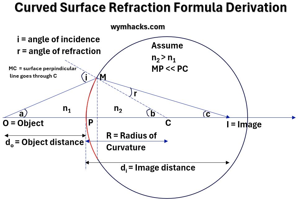
By drawing an oblique ray (OM in the drawing above), you can use Snell’s Law and some trigonometry to derive the Curved Surface Refraction Formula.
You can see the full derivation in this post: Lens Equations. The end result is the equation below.
Curved Surface Refraction Formula:
n2/di – n1/do = (n2 – n1)/R
- n = indices of refraction of each medium;
- R = Radius of Curvature;
- d = Image or Object distance to Optical Center.
Lens Maker’s Formula
In the drawing below, a bi-convex lens is represented by the sections of two circles.
Picture_Drawing for Lens Maker’s Formula Derivation
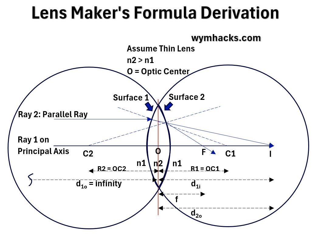
If we assume
- the lens are spherical so the Radius of Curvature will be the radius of the circle that the curves extend to,
- the 2 curved surfaces are not necessarily the same, and
- the width or thickness of the lens is much smaller than the Radius of Curvature.
- So the distances between O and the curved surfaces is negligible (say zero).
,we can
- start with two parallel rays of light (Ray 1 and 2),
- use the Curved Surface Refraction Formula,
- apply a little geometry and algebraic manipulation,
and ultimately derive the Lens Maker’s Formula.
You can see the detailed derivation in my post: Lens Equations.
Lens Maker’s Formula:
1/f = (n2/n1-1)(1/R1 – 1/R2)
- f = lens focal length;
- n = indices of refraction of each medium;
- R = Radius of Curvature of each surface
This applies to convex or concave thin lenses.
Check out the videos below for derivation of the equation and examples of how the equation can be used.
- Lens Maker’s Formula Derivation – Khanacademy.org
- Solved Example Lens Maker’s Formula – Khanacademy.org
- Michel van Biezen Physics Videos Using Lens Maker’s Equation
- See the “Physics – Optics: Lensmaker’s Equation” series (1 of 5)
Conclusion
- On a Macro level, assuming light travels in a straight line is valid and useful.
- Snell’s Law describes how light bends when it travels from one material to another (the ratio of the sines of the angles of reflection and incidence is constant).
- The Cornea and the Lens of the eye refract or bend light onto the back of our eyes (to the Retina).
- The Eye projects a Real Inverted Image to the Retina.
- Ray Diagrams of Biconvex and Biconcave lenses provide useful models for understanding the physics of light refraction.
- The Focal Point, F, of a lens is the point where parallel light rays converge after passing through a lens.
- The Focal Distance, f, is the distance from the Focal Point to the Optical Center of a lens.
- Lens Power is the Inverse of the Focal Distance: P = 1/f and is measured in Diopters (inverse meters).
- Ray Diagrams for various locations of Objects relative to the Focal Point F (for Biconvex and Biconcave Lenses) allow us to predict the location, size, orientation, and nature (real/virtual) of the image formed.
The
- Magnification Equation, the
- Thin Lens Equation, and the
- Lens Maker’s Equation
make it possible to accurately calculate and predict the properties of images formed by lenses.
Disclaimer: The content of this article is intended for general informational and recreational purposes only and is not a substitute for professional “advice”. We are not responsible for your decisions and actions. Refer to our Disclaimer Page.
