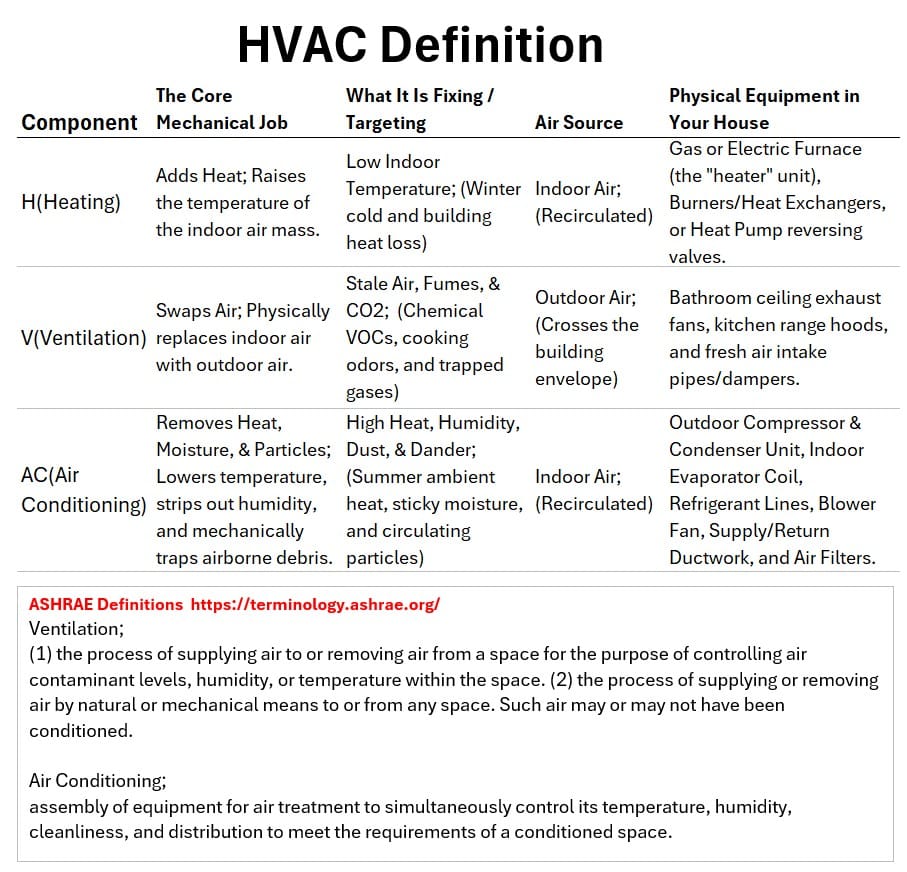
HVAC Definition
In this post , we are going to learn all about Heating, Ventilation, and Air Conditioning systems (HVAC).
Why?
Here are some possible reasons:
- Visualize and understand the beautiful and practical application of Physics and Thermodynamics to everyday life.
- Physics: The study of matter, energy, and motion
- and Thermodynamics: The Science of heat, work, and energy transformation.
- Many HVAC setups are costly to operate and repair. Understanding your system might save you a lot of money over the years.
- This is especially true for owners of traditional ducted split central cooling systems (e.g. 66% of US homes have centralized ducted AC systems).
- When you understand the baseline of how your system operates, you move from being a passive consumer to an informed owner.
- You will be better equipped to distinguish between a minor, routine repair and an impending mechanical failure, potentially saving thousands in unnecessary service calls or premature replacements
- You might be someone in the industry who wants to upskill by learning more about the thermodynamics of HVAC systems.
- Understand the global warming impact of HVAC applications.
- You might be a politician or a building manager or a home owner that want to do their part to reduce global warming.
- According to data from the U.S. Department of Energy (NREL), replacing a traditional fossil-fuel furnace with a modern heat pump slashes a home’s heating emissions by roughly 50%.
- Because space and water heating account for roughly 12% to 13% of all global greenhouse gases according to the International Energy Agency (IEA),
- scaling this 50% reduction globally would shave a massive 6% off total global emissions—an impact larger than eliminating every passenger car on earth.
What is an HVAC System?
Source of Definitions: ASHRAE ( American Society of Heating, Refrigerating and Air-Conditioning Engineers) ASHRAE Terminology A Comprehensive Glossary
Consider the sketch and table below.
Chart: HVAC Definition
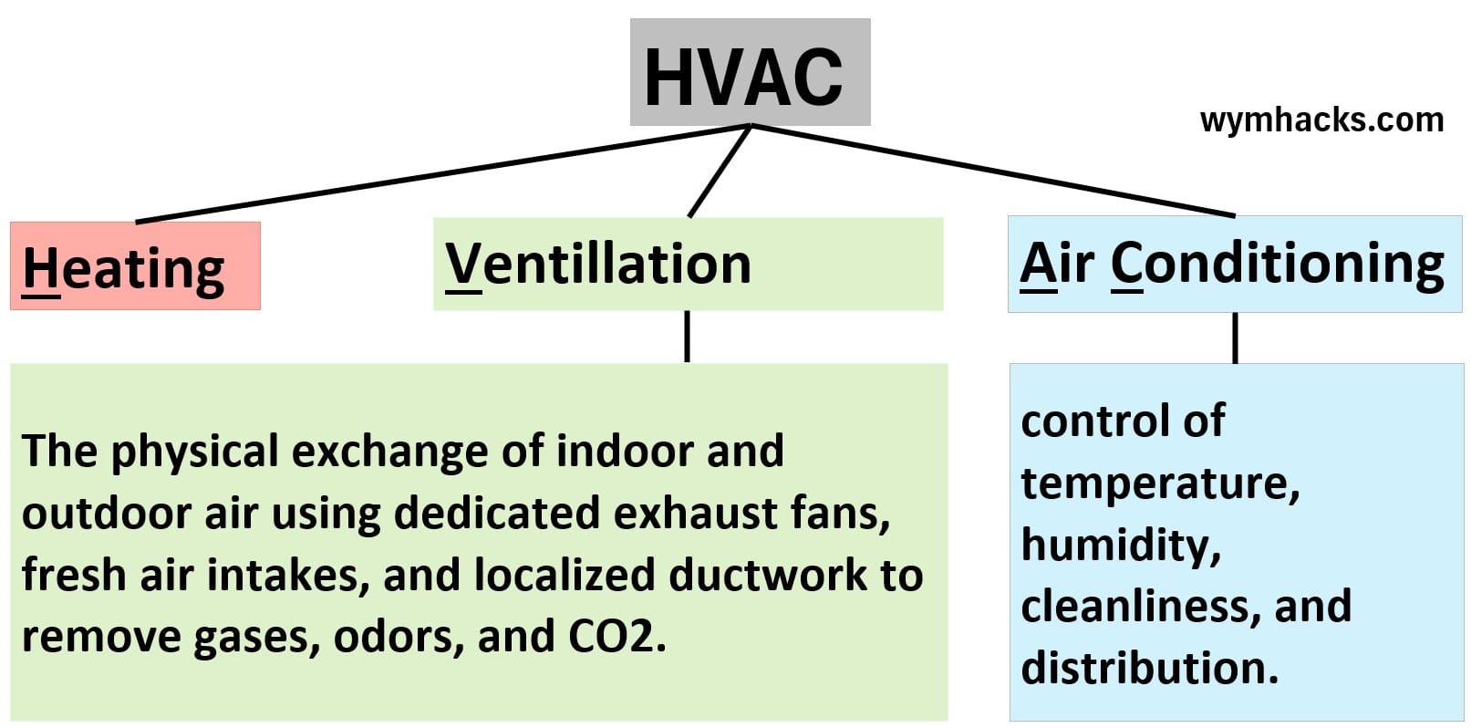
Table: Definition of HVAC
 An HVAC system is the integrated technology used to
- manage indoor air quality and thermal comfort
- by regulating temperature, moisture levels, and air circulation (or at the very least air movement and air filtering).
The primary functions of any HVAC system are:
H (Heating)
Heating means raising the indoor temperature either by:
- (a) generating thermal energy (like burning fuel or electrically heating elements…common in traditional US split central HVAC systems) OR
- (b) capturing and transferring thermal energy from the outdoors to the inside (via heat pump technology).
- A heat pump is smart refrigeration technology that can flip the functionality of its heat exchange equipment,
- giving cooling in the summer and reversing itself to provide heat in colder periods from a single outdoor unit.
- Heat pumps are increasingly used in the US and extensively used globally.
V (Ventilation)
I’m sticking with the ASHRAE definition here.
Ventilation is “(1) the process of supplying air to or removing air from a space for the purpose of controlling air contaminant levels, humidity, or temperature within the space. (2) the process of supplying or removing air by natural or mechanical means to or from any space. Such air may or may not have been conditioned.”
So according, according to ASHRAE, ventilation is strictly defined as the process of supplying outdoor air to, or removing indoor air from, a space by natural or mechanical means.
Its intentional engineering purpose is to control indoor air contaminant levels, humidity, and temperature.
Ventilation equipment is categorized into two mechanical strategies:
Exhaust Ventilation Hardware:
Localized systems designed to push contaminated indoor air out of the building envelope.
This includes bathroom exhaust fans, kitchen range hoods, and their dedicated, independent exhaust ductwork.
Supply & Balanced Ventilation Hardware:
Systems designed to intentionally bring fresh outdoor air inside.
- Fresh Air Intakes & Motorized Dampers:
- A dedicated duct running from the outdoors directly into the main AC return plenum, controlled by an electronic valve (damper) that opens to let outside air mix into the system.
- ERVs and HRVs (Energy/Heat Recovery Ventilators):
- Completely separate, dual-fan motorized units that simultaneously exhaust stale indoor air and pull in fresh outdoor air, passing them through a central core to swap heat so you don’t waste energy.
Note that, historically, most U.S. homes have no intentional system for bringing in fresh air; they rely on “infiltration,” meaning outside air accidentally leaks in through gaps in windows, doors, and walls while bathroom and kitchen fans exhaust localized moisture.
- However, because modern energy codes force new homes to be built airtight, builders are now legally required to install dedicated mechanical ventilation—like fresh air intakes or ERVs—to keep indoor air from becoming toxic.
AC (Air Conditioning)
According to ASHRAE, air conditioning is “the process of treating air to meet the requirements of a conditioned space by controlling its temperature, humidity, cleanliness, and distribution.”
- Regardless of the specific configuration, cooling is always provided by using refrigeration technology to capture heat indoors and reject it outdoors.
- The cooling can be provided
- by heat pump technology (like in a typical European dwelling) where both heating and cooling is provided by the refrigeration equipment) OR
- by more traditional systems (like a US split central HVAC system) which utilize refrigeration technology to only supply the cooling.
Note that the network of supply and return ductwork running through a residential home, commercial office, or any indoor structure belongs entirely under the “distribution” branch of the air conditioning system.
Because these ducts solely recirculate, filter, and deliver the air mass already trapped inside the occupied spaces back to the central heating and cooling equipment, they function as an internal thermal transit loop for the AC rather than an exchange mechanism for fresh outdoor ventilation.
Summary
Don’t worry at this point if the definitions seem cumbersome.
By the time we’re done, it will all be crystal clear.
For now, lets be sure we understand that:
- HVAC systems are the equipment and associated technology that provide heating and cooling for homes and buildings.
- Cooling is always provided by refrigeration equipment that extracts heat from the indoors and rejects it to the outdoors.
- Sometimes the heating is provided by external systems utilizing fuel gas combustion or electrical heating of elements.
- Sometimes the heating is provided by the refrigeration technology itself, essentially running in reverse from its cooling mode.
A heat pump is the generic descriptor for refrigeration technology and equipment capable of providing both heating and cooling.
- In cooling mode, indoor heat is captured and rejected outdoors.
- In heating mode, the cycle reverses so that outdoor heat is captured and injected indoors.
- Generally, a system is not described as a heat pump if it only provides cooling or heating (i.e. one of the two).
- However, there are dedicated, non-reversing heating systems that are commercially classified as heat pumps because they use a refrigeration loop specifically to produce heat:
e.g. Heat Pump Water Heaters, Dedicated Heat-Recovery Chillers, and Exhaust-Air Heat Pumps.
HVAC Overview: Split Central AC With Fossil Fuel Heating
There are many types of HVAC systems applied across the world (see Appendices 4 ,5, 6, and 7 ) and several factors will determine which type will be employed.
Four very important factors are:
- Energy Infrastructure & Utility Costs (e.g. is fuel gas readily available and cheap?)
- Existing Home Architecture & Ductwork (many homes across the world do not have ductwork due to age or other factors)
- Local Climate Extremes ( cold climates will need more robust and efficient heating than hot climates; see climate zones information in Appendix 7)
- Local building requirements which might be influenced by environmental regulations.
To explain HVAC concepts, I’m going describe a standard split central ducted AC and furnace system—partly because it’s what I live with (US Gulf Coast), but mostly because it’s spread-out layout makes the mechanics of refrigeration easy to visualize.
- Just keep in mind that across Europe, Asia/Middle East, and Latin America, central ducted systems are the exception, not the rule.
We know that a home’s HVAC system is the integrated technology used to manage indoor air quality and thermal comfort by regulating temperature, moisture levels, and air circulation.
An AC cooling/heater is a heat transfer machine and its function is to:
- Cool:
- capture heat and water from indoor air (air cooling and dehumidification) and
- reject the heat and water to the outside of the house (the environment).
- Heat:
- Heat indoor air via an external heating source (like burning fuel gas or electrical elements) or
- by using the refrigeration equipment in reverse (heat pumps; more on this later).
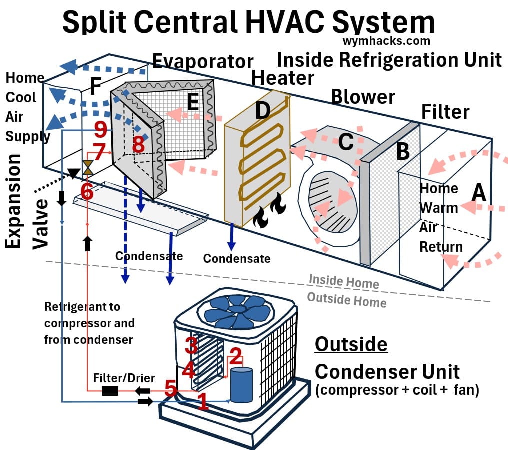
Below I’ve provided a simplified sketch of a “typical” Gulf Coast USA home (IECC Zone 2) HVAC system split into inside and outside “units”.
Picture: Overall View of a Typical Split Central Home HVAC System
Inside AC Unit
Purpose: Extract (capture) heat (cool) and remove water (dehumidify) from indoor air.
I show the inside unit as a horizontal-attic-installed unit with circulating indoor air flow being cooled as it flows from A to F and back to A.
A blower (a fan basically) sucks the air in through a filter and pushes it across an evaporator (a heat exchanger that contains cold refrigerant on the other side) which
- dehumidifies it (water vapor in the air condenses) and
- cools it (so you enjoy that cool dry air from your ac)
The horizontal attic configuration is common in homes that don’t have basements (homes in the southern US for example).
- Vertically installed inside units can be installed in both attics (if they are big enough) and basements (more common in northern US homes)
- They all fundamentally work the same way and, typically, the equipment configuration ‘order’ is the same.
Inside Heater Unit
Purpose: Heat the indoor home air by contacting a gas fired or electrical heater.
These heater systems are often integrated into the same inside unit that contains the evaporator (see D in the schematic above).
Understanding this integration is key, as modern systems often share the same air handling units, blowers, and ductwork to distribute both cooled and heated air.
When the heater is turned on, the ac components (inside and outside) are turned off (i.e. refrigeration is not flowing , evaporating or condensing).
The air flow path remains the same (ABCDEF) and it still flows through all the inside equipment units (except there is no cooling happening).
We’ll see later that cleverly designed refrigeration equipment can be used to supply this heating (heat pump concept).
Outside AC Unit
Purpose: Reject heat from the refrigerant by compressing it and condensing it.
The outside unit is connected to the inside unit via copper tubing which contains refrigerant.
The refrigerant evaporates in the evaporator (cooling the indoor air) and then flows to the outside unit where it is liquified by compression and outside air cooling.
Why the Split Design?
The “split” design is popular because it offers a balance of efficiency and comfort.
By separating the mechanical parts (compressor/condenser) from the air delivery parts (blower/ducts), the system allows for quieter operation indoors while keeping the bulky machinery out of your living space.
Ok, you now have a nice general idea of how an HVAC might operate.
Let’s dig deeper.
Mechanical Process Description of a Split Central Home AC System
In this section we’ll detail out what we broadly described in the previous section.
In the drawing below, the inside and outside refrigeration units are presented as you might see them in/at your home (although the inside unit will be enclosed in a long insulated rectangular box so you wont be able to see the components from the outside).
Drawing: Split Central HVAC System: Equipment Layout
Inside Unit (A – F)
In cooling mode, the inside unit draws in warm, humid air from your home and passes it over the cold evaporator coils, where the refrigerant absorbs the heat and carries it away to the outdoor unit.
Once cooled and dehumidified, the air is blown back into your living spaces to repeat the cycle.
In heating mode, the inside unit draws in air from your home and heats it up (the evaporator is not operating in this mode).
The inside unit is shown as a rectangular box which ,for a split HVAC system, is called the furnace and evaporator coil cabinet.
- The box (metallic) is enclosed in some kind of insulation so you cant see these components from the outside.
- I show it as a horizontal configuration designed to fit into tight home attic space.
- Note that these can (are) configured vertically with enough attic space or if the home has a basement (which are not common in the southern US).
Let’s review the internal components of this insulated enclosure (in order of airflow).
Return Air Plenum (A)
This is the pressurized box where all the return ducts from your house meet before entering the unit.
Filter (B)
The filter is placed here to catch dust before it can coat the blower motor or the sensitive fins of the coils.
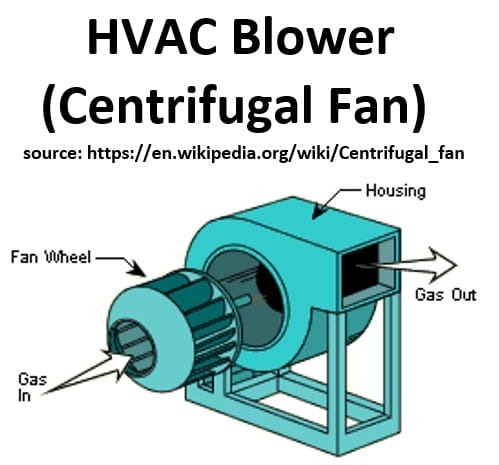
Blower (C)
- The blower fan pulls air through the filter and pushes it through the rest of the cabinet (box).
- It uses an electric motor to spin a fan—usually a “squirrel cage” centrifugal fan—which creates a pressure differential.
Picture: Components of a centrifugal fan
Heater (D)
- The HVAC system is either in cooling mode or heating mode.
- In heating mode, the refrigeration/cooling system is turned off.
- The heating equipment is typically one of two designs: Electric heat strips or a gas fired heat exchanger.
- For a gas fired heat exchanger, the hot combustion gas flows inside heating tubes and heats up the air flowing on the outside of the tubes.
- The combustion gas is then exhausted to the atmosphere via a vent.
- In most southern US split HVAC systems, the heater is positioned after tler (for gas fired furnaces)
- In some southern US installations, the evaporator coil is actually placed before the Heater (if using electric heat strips) to prevent the cold, damp air from blowing directly onto the heater elements, which can cause corrosion over time.
In a vertical assembly, if you open up the cabinet doors, you’ll see most of the components drawn below.
Horizontal assemblies will have the same sequence of burners and coils but pitch adjustments are needed to ensure adequate water draining (from secondary coils).
Picture: Simplified Vertical HVAC Gas Heater Assembly
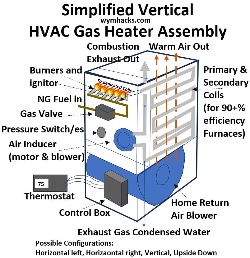
In the heater startup sequence below , I’ll introduce you to the major components in this system.
Refer to the simplified drawing above as needed.
Heater_Control Board
- It coordinates the timing and execution of the heating cycle to ensure efficiency and safety.
- Signal Processing: It receives a low-voltage signal from the thermostat calling for heat.
- Sequence Management: It triggers components in a specific order: first the inducer motor (to clear exhaust), then the igniter, and finally the gas valve.
- Safety Monitoring: It constantly monitors sensors (like the flame sensor and limit switches).
- If it detects a problem—such as the gas failing to ignite—it shuts the system down to prevent a gas leak or overheating.
- Blower Control: After the heat exchanger warms up, the board activates the main blower fan to circulate air through your home.
Heater_Induction & Venting
- When you turn on the heat and set a temperature target on your Thermostat,
- the Inducer Draft Motor is energized.
- This small blower clears the Primary and Secondary Coils (Heat Exchangers) of residual gases (pushes them out through the exhaust) and
- ensures a constant flow of air (O2) for combustion.
Heater_Safety Verification
- The Pressure Switch, which is defaulted “open”, will “close” when it senses a vacuum created by the Inducer.
- The pressure switch acts as a safety gate that blocks the ‘all-clear’ signal to the Control Board, preventing ignition if it doesn’t sense a vacuum from the exhaust fan.
- Some examples of things that could cause a loss of vacuum are:
- Exhaust obstruction, intake blockage, drainage failure (water from exhaust gas water condensing in the secondary coil), mechanical inducer fan failure, coil crack or hole, etc.
Heater_Ignition Prep
The Igniter (usually a Silicon Nitride or Carbide element) begins to glow white-hot.
Heater_Combustion
- Fuel Release: The Gas Valve opens, releasing a metered flow of fuel (typically natural gas) into the Burners.
- Ignition: The air-gas mixture passes over the Igniter, lighting the fuel to create a steady flame at each burner head.
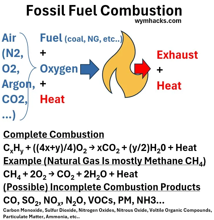
- Combustion of fossil fuel (like natural gas) will produce CO2 , Water, and Heat (as well as other produces of incomplete combustion)
- If natural gas were to combust ideally and completely (it wont), the equation describing the combustion is CH4 + 2O2 = CO2 + 2H2O + Heat
- This is important to understand because if the heater is efficient enough (90+%) the exhaust gases will be cooled to such a degree that water will start condensing and must be drained out.
Schematic: Fossil Fuel Combustion
Heater_Flame Safeguard
- Within seconds, the Flame Sensor must detect an electrical current through the fire.
- If it doesn’t “see” the flame, it closes the gas valve immediately to prevent a leak.
Heater_Primary Heat Exchange
- Each burner shoots its flame into a dedicated Primary Coil.
- In the simplified drawing above I show only a single burner dedicated coil.
- These individual tubes absorb the initial, intense “dry heat” from the combustion process.
Heater_Secondary Heat Exchange
- The gases then move into a Secondary Condensing Coil (usually a dense grid of smaller tubes).
- Here, the system extracts the remaining heat until the exhaust cools significantly, causing the gases to condense into liquid water.
Heater_Exhaust Collection & Drainage
- The cooled gases and the resulting water gather in the Collector Box (not shown in my simplified drawing).
- The liquid water is drained out through a condensate line, while the Inducer Fan pulls the remaining exhaust fumes out to be vented safely outside the house.
- The Secondary Coil is what makes a furnace “high-efficiency.”
- In older furnaces, the emitted exhaust was still very hot (and full of wasted energy).
- In a 90%+ efficiency system, that Secondary Coil squeezes extra heat out of the air and the exhaust became cool enough to turn into water
- This is why the collector box needs a drain.
Heater_Air Distribution
- Once the heat exchangers are sufficiently hot, the main Blower Motor turns on.
- It pushes cool house air over the exterior of the exchangers, picking up heat before heading into the ductwork.
Heater_Shutdown
- When the thermostat is satisfied, the Gas Valve closes.
- The Inducer Motor performs a “post-purge” to clear exhaust, and
- the Blower Motor continues to run for a few minutes to dissipate the remaining heat from the metal exchangers into your home.
You can watch these descriptive videos that describe HVAC heater components and what they do:
- How A Gas Furnace Works (Animated Schematic): Alpine Intel
- How a Furnace Works – Furnace Sequence of Operation : Word of Advice TV
- Explaining “Gas Furnace Basics, Operation, Efficiency, Parts” to Your Apprentice! AC Service Tech LLC
- The AC Service Tech LLC instructor is awesome
Evaporator Coil (E)
Picture: Vertical HVAC Evaporator Coil
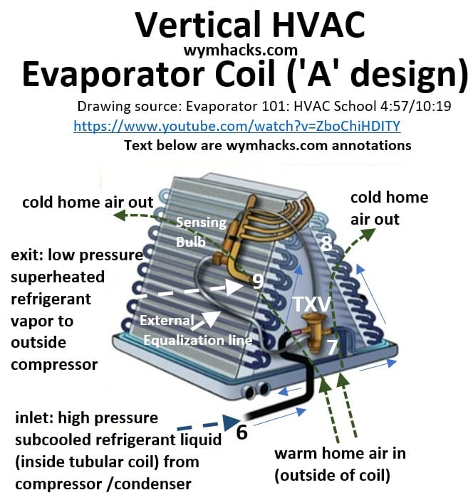
“A” Coil
- The Evaporator Coil will have an “A-coil” or “Slab coil” design.
- In a vertical assembly, it will look like the picture. In a horizontal unit, its position will be such that it still accepts the warm home air from the inside out.
Home Air is Cooled and De-humidified
- Air from the home flows across the outside of the coil and is cooled and dehumidified by refrigerant that is flowing inside the coil.
Refrigerant TXV – Thermal Expansion Valve
I’ve provided two drawings (1 and 2; both describing the same thing) that you can refer to as you read this section.
- Compressed , cooled and dry refrigerant liquid (6) is de-pressured (throttled) across an expansion valve (7) into a liquid/vapor mixture.
- This expansion valve is called a TXV (Thermal Expansion Valve)
Schematic: Home AC Refrigeration Loop: TXV Thermal Expansion Valve (drawing 1)

Schematic: Home AC Refrigeration Loop: TXV Thermal Expansion Valve (drawing 2)

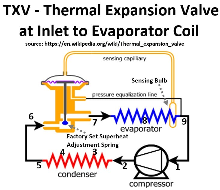
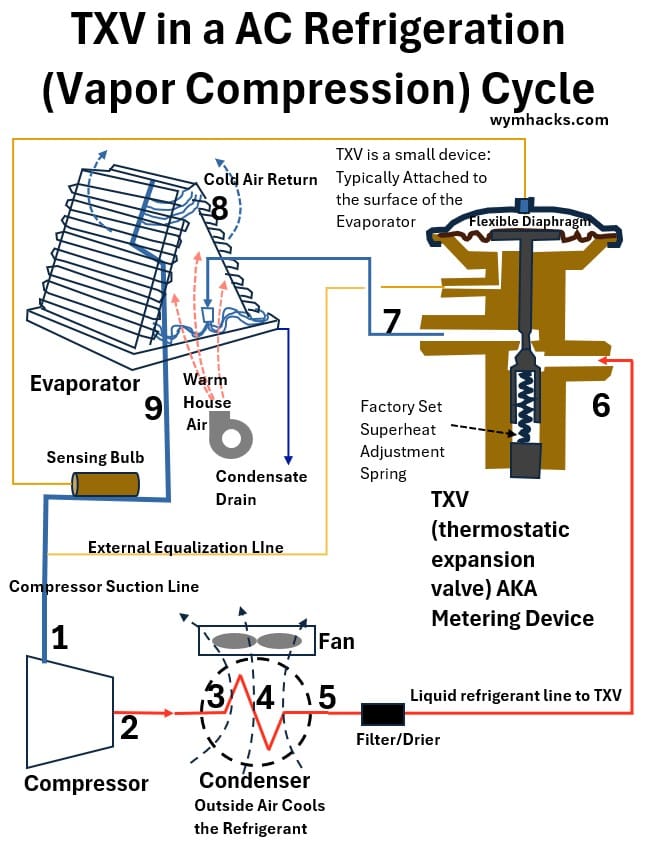
- The TXV is a self-regulating device (6 and 7) that constantly adjusts the flow of liquid refrigerant into the evaporator coil (8) to maintain a precise “superheat” temperature target (at 9).
- The TXV will be located on the face of the evaporator coil assembly.
- Superheat is a fancy word for the temperature of the dry vapor refrigerant leaving the evaporator (we always want dry vapor because any liquid will damage the downstream compressor).
- The TXV accomplishes this through a continuous tug-of-war across a flexible internal diaphragm.
- A sealed sensing bulb clamped to the evaporator outlet pushes down to open the valve,
- while the evaporator’s own internal pressure (equalization line attached at 9) combined with a factory-set mechanical spring pushes up to close it.
- Because the bulb is a closed, fixed-volume container packed with a saturated (liquid + vapor) mixture,
- any temperature increase at the evaporator outlet pipe (at 9) causes its (the bulb’s) internal pressure to skyrocket much faster than the evaporator outlet pressure (which actually doesn’t move much and is essentially constant except for line losses),
- overpowering the spring and opening the valve to flood the coil with more cooling refrigerant liquid.
- Conversely, if the pipe gets too cold, the bulb pressure drops, allowing the spring to push up and throttle the valve closed to prevent liquid from dangerously flooding back to the compressor (liquid slugs will damage the compressor).
Evaporator Process Flow
- After getting throttled through the TXV (6 and 7), the lower pressure refrigerant liquid/vapor mixture enters the evaporator where it absorbs heat from warm indoor air flowing across the outside of the evaporator.
- The refrigerant will eventually becomes a dry superheated vapor (8 to 9) as it exits the evaporator.
- This dry lower pressure vapor refrigerant then flows to the outside unit for compression and condensation (1 through 5).
- and the cycle repeats.
Supply Air Plenum (F)
This final pressurized box distributes the newly cooled (or heated air when in heating mode) air into the individual supply ducts leading to your rooms.
Outside Unit (1 – 5)
The outdoor unit completes the cooling cycle by rejecting the heat captured from inside-home air.
Recall we noted that the “split” design is popular because it offers a balance of efficiency and comfort.
By separating the mechanical parts (compressor/condenser) from the air delivery parts (blower/ducts), the system allows for quieter operation indoors while keeping the bulky machinery out of your living space.
- Low-pressure dry refrigerant vapor carries the heat captured from your indoors to the outdoor compressor (1 and 2) and to the outdoor condenser coil (3 and 4).
Picture_Compressor / Condenser Unit (Outside Split HVAC Unit)
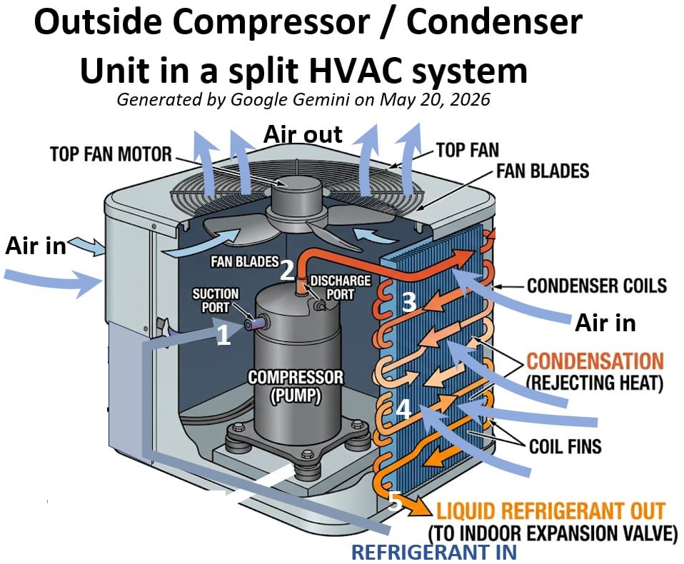
- In this compressor/condenser unit , a compressor pressurizes or “squeezes” the refrigerant gas (1 and 2), and a large fan pulls outside air across the coil to remove the heat from the refrigerant and into the environment.
- The compressor is the primary driving force of the refrigeration cycle.
- It functions as a vapor pump, responsible for circulating the refrigerant and creating the pressure differential necessary for heat transfer to occur.
- The compressor takes low-pressure vapor from the suction line (1) and mechanically compresses it into a high-pressure, high-temperature gas (2).
- This is critical because the refrigerant’s boiling point increases with pressure;
- by raising the pressure, the compressor ensures the refrigerant is hot enough to reject heat to the outdoor air, even on a hot day.
- It establishes the flow rate of the refrigerant through the entire system.
- Without the compressor, the refrigerant would remain stagnant, and no heat exchange would take place.
- The compressor contains specialized oil (often POE or PVE oil) that circulates with the refrigerant to lubricate moving parts.
- This oil must be compatible with the specific refrigerant used (e.g., R410A or R32).
- Home AC system commonly employ scroll type compressors.
Picture: Danfoss Scroll Compressor (Single Speed)
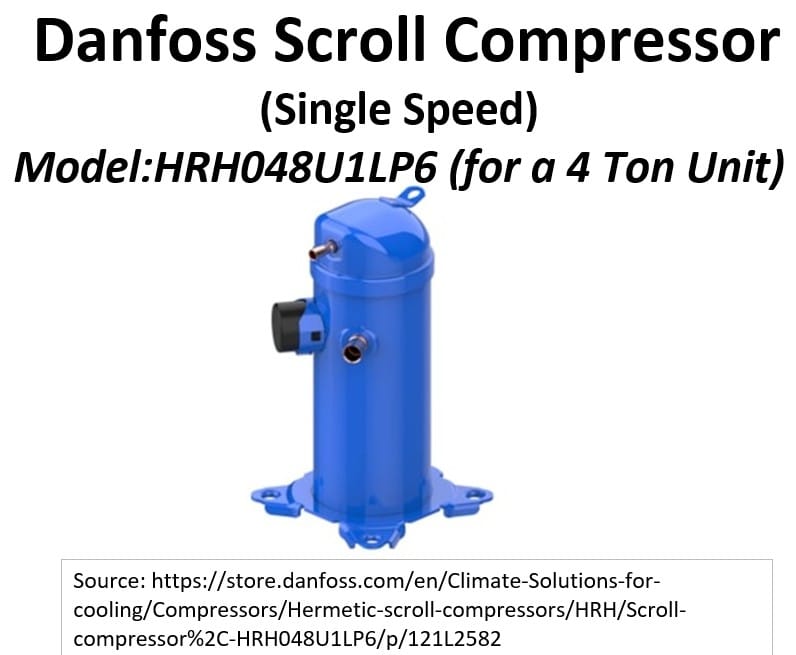
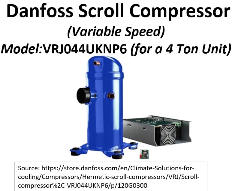
Picture: Danfoss Scroll Compressor (Variable Speed)
- A scroll compressor compresses gas using two interlocking, spiral-shaped scrolls.
- One scroll remains completely stationary, while the other moves in an eccentric orbit without actually rotating.
- This orbital movement traps pockets of gas at the outer edges of the spirals and continuously squeezes them toward the center, increasing the pressure before discharging it
- Standard Scroll Compressors run at a fixed, single speed, turning completely on or off to maintain temperature, which makes them highly durable but less energy-efficient.
- Digital Scroll Compressors run at a constant speed but dynamically separate their internal spiral components to temporarily stop pumping refrigerant, matching your home’s cooling needs by alternating between active and idling states.
- Inverter (Variable-Speed) Scroll Compressors electronically adjust the speed of the motor itself, slowing down or speeding up smoothly to precisely track your home’s real-time temperature demands with maximum efficiency.
See this video for more on scroll compressors :
- The refrigerant exits the condenser as a cooled high pressure liquid refrigerant.
- The liquid refrigerant flows back to the TXV and the evaporator inside the house to start the cooling loop all over again.
Check out these two nice videos:
Inside and Outside Unit Piping Connections
Refrigeration Loop Suction Line
- This is the larger, insulated copper pipe entering the outdoor unit.
- It carries low-pressure, low-temperature refrigerant gas back from the indoor evaporator coil to the outdoor unit so the compressor can pump it again.
- Because the gas inside is cold, this pipe will sweat if exposed to air.
- It is always wrapped in thick, black foam insulation to prevent condensation and keep the refrigerant from absorbing heat from the outside air.
Refrigeration Loop Discharge Line
- This is the smaller, uninsulated copper pipe leaving the outdoor unit.
- After the outdoor unit compresses and cools the refrigerant, it turns into a high-pressure, warm liquid.
- This thin pipe carries that liquid refrigerant back inside to cool the home.
- A bullet shaped cylinder called the Filter/Drier is installed directly inline on this narrow pipe—often right outside the metal cabinet.
- It contains a desiccant material that traps tiny bits of debris, solder scale, or moisture before the liquid refrigerant reaches the indoor expansion valve, preventing clogs and internal damage.
Water Drains
An HVAC system generates water from two main sources: cooling condensation in the summer and heating condensation in the winter.
- During the summer, the air conditioner acts like a giant dehumidifier, squeezing moisture out of humid indoor air as it passes over the cold evaporator coils.
- In the winter, if you have a high-efficiency (90%+) gas furnace, the system extracts so much heat from the exhaust gases that the vapor condenses into liquid water inside a secondary heat exchanger.
Both sources produce gallons of water daily that must be safely funneled out of your home through dedicated PVC drain lines to prevent accidental flooding and water damage.
Simplified Diagram Showing Overall HVAC System
The schematic below depicts a typical split home central HVAC system showing both heating and cooling components.
Schematic: Split Home Central HVAC System
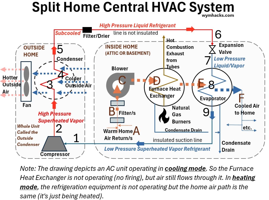
HVAC systems are going to be in either heating mode or cooling mode.
- Loop 1 through 9 is the closed refrigeration loop dedicated to cooling your home air during the summer (typically).
- If we start at 1, the four stages of refrigeration are called
- compression (1,2),
- condensation (3,4,5)
- These occur outside the house
- expansion (6,7)
- evaporation (8,9)
- These last two occur in the inside unit (in the attic or basement of a house)
- If we start at 1, the four stages of refrigeration are called
- Loop A through F is the path your home air takes. Notice it follows the same path in both heating and cooling modes.
- The blower operates in both heating and cooling mode.
- In heating mode, the outside compressor and condenser fan are turned off and the heater is activated (gas fired or electric coils).
- The cold home is warmed as it flows through the active heater and the inactive evaporator.
- In cooling mode, the air flows through the same path but now flows through an inactive heater before it gets cooled through the evaporator.
Mollier
If you want to truly understand how refrigeration works, there is one tool you need to become familiar with: the Mollier Diagram.
It is a diagnostic map and design cheat sheet for HVAC professionals (and for curious people like you), that shows exactly what is happening to the refrigerant at each point of the cycle.
The Mollier diagram is named after Richard Mollier (1863-1935), a German who pioneered experimental research on thermodynamics associated with water and steam.

Picture Source: https://commons.wikimedia.org/wiki/Category:Richard_Mollier
It is a graphical representation showing the relationship between enthalpy, entropy, temperature, pressure and quality of a substance (e.g. a refrigerant or steam).
If we jump straight into a Mollier diagram without first understanding the thermodynamic properties listed above, we’re not really going to “get it”.
Therefore, before we can unlock the Mollier, we are going to review/explain/discuss 5 key concepts:
- Thermodynamic states: the physical condition of a substance
- i.e. is the substance hot or cold; high pressure or low pressure; vapor or gas or a mixture; how energy or low energy etc.
- The Ideal Gas Law: The physics of how pressure, volume, and temperature interact when we squeeze or expand a gas.
- Boiling Point Curves: How changing the pressure of a refrigerant completely changes the temperature at which it boils or condenses.
- The First Law of Thermodynamics for Flow Systems: How energy is conserved and transferred as a fluid moves through pipes, compressors, and valves.
- Temperature-Enthalpy (T-H or T-h) Chart: The stepping-stone graph that visually maps out ‘sensible heat’ (changing temperature) versus ‘latent heat’ (changing state at constant temperature).
Once we understand these concepts, the Mollier diagram becomes much more intuitive.
Let’s start by discussing thermodynamic states.
Thermodynamic States of the Refrigerant
The schematic below shows a home ac refrigeration cycle indicating the state of the refrigerant at each location.
Schematic: Split Home Central Air Cooling Cycle (Vapor Compression Cycle)
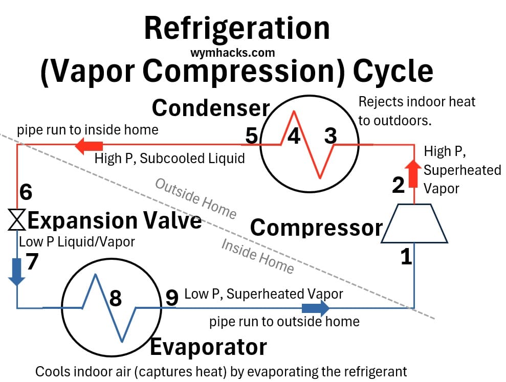
The refrigeration cycle operates as a closed loop that continuously alters the “thermodynamic state” of the refrigerant to transfer heat.
The thermodynamic state is the unique combination of pressure, temperature, and phase (liquid, vapor, or a mix of both) that the refrigerant holds at that precise moment.
- It begins as the compressor intakes a low-pressure superheated vapor and performs mechanical work to compress it into a high-pressure, highly superheated vapor, elevating its temperature above ambient outdoor conditions.
- superheated vapor = a dry vapor whose temperature is higher than its boiling point at its current pressure.
- This hot gas flows into the outdoor condenser coil, where it undergoes isobaric (constant pressure) heat rejection and changes phase, exiting the coil as a high-pressure subcooled liquid.
- subcooled liquid = liquid refrigerant whose temperature is lower than its boiling point at its current pressure.
- This liquid is then throttled through a metering device (the TXV valve), dropping sharply in pressure and temperature to become a low-pressure, boiling liquid-vapor mixture.
- A real world example of this throttling process would be a hair spray can (high pressure liquid escapes out the spray head as a fine mist).
- Finally, as this cold mixture passes through the indoor evaporator coil, it absorbs heat from the indoor air.
- During the boiling phase change, this happens isobarically (constant pressure) and isothermally (constant temperature).
- Once all the liquid has boiled away into a dry vapor, the temperature begins to rise slightly, superheating the low-pressure gas just before it enters the compressor to complete the cycle.
The Journey to the Mollier Diagram
What you just read is the mechanical sequence of events in a refrigeration cycle.
But if you look closely, it brings up some interesting questions.
- Why does compressing a gas make it hot?
- Why does dropping the pressure at the TXV valve make it freezing cold?
- And how can the refrigerant absorb massive amounts of indoor heat in the evaporator without its temperature changing at all while it boils?
To answer these questions and unlock the Mollier Diagram—the ultimate diagnostic map that visualizes this whole cycle—we need to understand the fundamental laws of physics ruling this system.
Over the next few sections, we are going to build that foundation step-by-step.
Let’s start with the Ideal Gas Law.
Boiling Point Curves (Pressure Temperature (P-T) Charts)
To understand how a refrigeration cycle manipulates heat, we must first look at how a refrigerant behaves when it changes phase from a liquid to a gas.
In everyday experience, we tend to think of boiling point as a fixed number—such as water boiling at 100°C.
In refrigeration, however, temperature is only half of the story.
The boiling point of any fluid is directly dependent on the pressure exerted upon it.
If you raise the pressure, the boiling point goes up; if you lower the pressure, the boiling point goes down.
The Pressure-Temperature (P-T) Curve is the chart that maps this exact relationship.
It serves as our baseline by showing the precise saturation point—the boundary where a refrigerant transitions between liquid and vapor at any given pressure level.
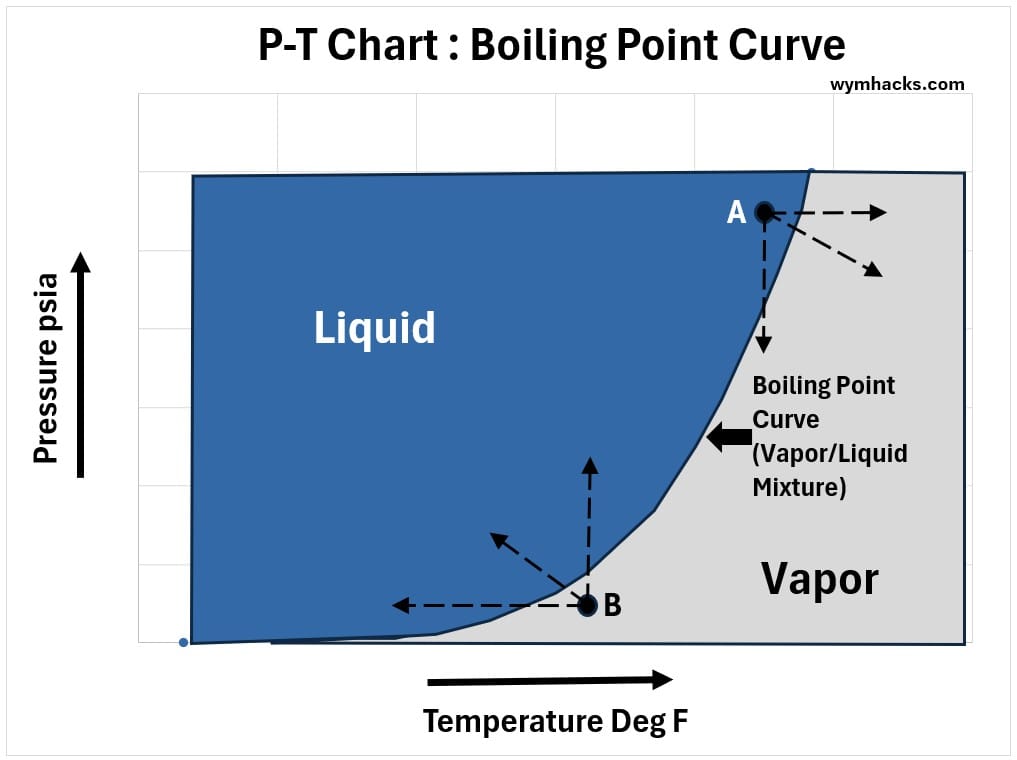
The chart below represents a generic P-T phase diagram:
The Phase Boundary (Boiling Line): The curved line represents the liquid-vapor equilibrium.
At any point along this line, the substance exists as a boiling mixture of both liquid and vapor.
Pressure-Temperature Relationship: The boiling point temperature increases concurrently with an increase in pressure.
Liquid at Point A, for example, can be converted into vapor by:
- Increasing Temperature at a constant Pressure (moving horizontally to the right).
- Decreasing Pressure at a constant Temperature (moving vertically downward).
- Simultaneously increasing temperature and decreasing pressure (moving diagonally downwards).
Vapor at Point B can be condensed back into a liquid by reversing any of the processes above (decreasing temperature, increasing pressure, or both).
Chart: Boiling Point Curve : P-T Chart
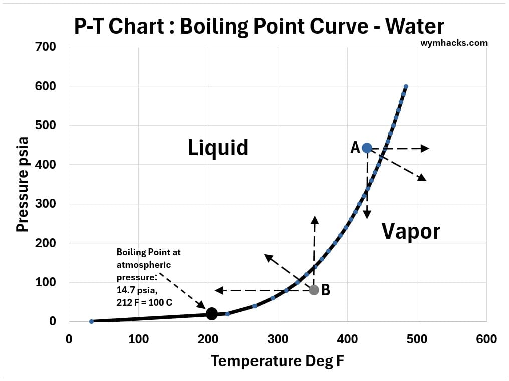
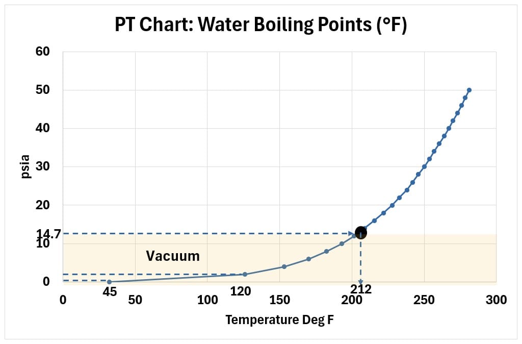
The boiling point curve for water is shown below.
Chart Boiling Point Curve : P-T Chart (Water)
In the chart below we show the boiling point curves for R410A and Water plotted on the same axis.
Chart: Boiling Point Curve : P-T Chart (R410A Refrigerant and Water)
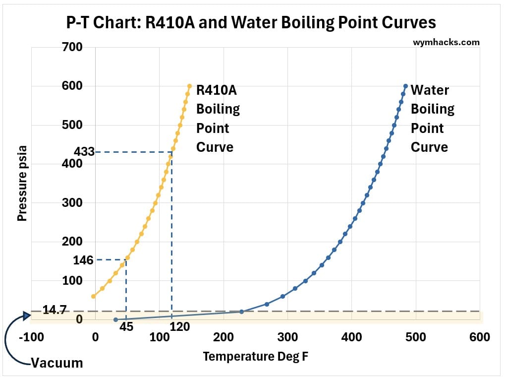
When you plot the boiling curves of water and R410A on the same axis, the stark contrast explains why we use specialized refrigerants for HVAC service instead of water.
- To absorb heat from a typical 21°C (70°F) room, a refrigerant needs to boil at a much lower temperature—usually around 4°C to 7°C (40°F to 45°F).
- As the chart demonstrates, water cannot boil at those temperatures unless the system pulls an extreme, near-total vacuum.
Chart: Boiling Point Curve : P-T Chart (Water – Vacuum Region)
- Conversely, R410A boils at 45F under a highly manageable, stable pressure of about 146 psia.
- Furthermore, if we look at the low-temperature side of the chart, water freezes solid at 0°C (32°F), which would completely block the system.
R410A remains a highly efficient fluid well into sub-zero temperatures, allowing HVAC systems to operate reliably across a vast range of environmental conditions without the risk of freezing or requiring massive, low-pressure volumetric equipment.
Key takeaways
- If we look at the P-T diagram for R410A, we see a similarly shaped saturation curve—but it is shifted to a completely different region of the chart.
- Unlike water, which requires extreme heat or low pressure to vaporize, R410A is engineered so that its saturation curve sits exactly within the temperature and pressure ranges of a standard residential AC system.
- The Pressure Problem:
- Water requires a vacuum to boil at air conditioning temperatures
- R410A operates at positive, stable pressures.
- Volume Problem:
- Water vapor at near-vacuum pressures expands to massive volumes, requiring an impractically large compressor.
- R410A vapor is dense, allowing for compact equipment.
- The Freezing Problem:
- Water turns to ice at 0°C, while R410A continues working seamlessly
Ok, nice. We are making progress.
Now it’s time to do a little heavy lifting in order to understand some key scientific terms which will “open up” our understanding of the physics of refrigeration.
First Law of Thermodynamics for a Steady State Flowing System
Note: Refer to Appendix 1 and my blog post: First Law of Thermodynamics for additional details on internal energy, enthalpy, and the first law.
In this section we are going to start with the First Law of Thermodynamics for a closed system and then apply it to a flowing system (like a refrigeration loop).
Because the refrigerant is moving and changing pressure, it possesses two distinct types of energy:
- Internal Energy: The thermal energy of the molecules themselves.
- Flow Work: The mechanical energy required to push the fluid through the system.
Instead of tracking both separately, thermodynamics gives us a very useful shortcut called the Enthalpy.
1st Law for a Steady State Flowing System
Lets start with First Law of Thermodynamics equation for closed (constant mass) systems:
(1) ΔU + ΔKEext + ΔPEext = +-Q+-W (closed system)
Note: The variables Q and W represent absolute positive magnitudes. The physical direction of the energy transfer (into or out of the system) is explicitly dictated by the algebraic sign (+ or -) placed in front of them (for example +Q is heat into system and -W is work done by the system).
where
- U = the total Internal Energy = sum of all internal kinetic and potential energies = ΣKEint +ΣPEint
- ΣKEint = sum of all Kinetic Energies of the atoms and molecules (internal)
- Kinetic energy is the energy of motion (linear (translational) or rotational).
- ΣPEint = sum of all Potential Energies of the atoms and molecules (internal)
- Potential energy is stored energy that an object possesses due to its position, structure, or state, giving it the potential to do work.
- ΔKEext+ ΔPEext are the sum (Σ) of all the external (macroscopic) kinetic and potential energies.
- Q and W are the heat and work being added to or subtracted from the system.
- Heat Q is energy transferred between objects (or systems) because of a temperature difference (moving from hot to cold).
- Work W is energy transferred by a force acting through a distance (like a piston compressing gas).
- Q and W are energy in transit and have the same unit of energy (in SI units, the Joule).
- i.e. Systems cant contain heat or work. They only show up when energy is crossing a boundary.
- (+) means Q or W is being added/done to the system e.g. +W is work done to the system
- (-) means Q or W is being subtracted from/done by the system e.g. -Q is heat leaving the system
Let’s expand the total work term (W) into two parts:
- Flow Work: The work done by pressure to push a unit mass of fluid into and out of the system, expressed as P1V1 -P2V2 .
- Shaft Work (Ws): All external, non-flow work forms per unit mass (e.g., turbines, compressors, or pumps or even electrical).
By substituting this back into the energy balance and moving the flow work terms to the energy side, we pair them with internal energy (U):
where Δ(PV) = P2V2 – P1V1
We now need to define an important term that we will utilize in our final expression.
Enthalpy is exactly defined as
(4) H = U + PV
Refer to Appendix 1 for how we can derive this expression.
- The Enthalpy (H) of a system is the sum of its internal energy (U) and energy required to occupy space (PV = Pressure x Volume)
or stated a little more explicitly,
- The Enthalpy (H) of a system is the total energy contained within it—defined as the sum of its internal energy (U) and the energy required to maintain its volume against its surrounding pressure (PV).
Substitute H for U + PV in the energy equation (3):
(5) ΔH + ΔKEext + ΔPEext = +-Q +-Ws
Assuming external energy changes (kinetic and potential energy) are negligible (ΔKEext ≈ 0 and ΔPEext ≈ 0) — as is true for a vapor compression refrigeration loop —the energy equation simplifies to:
(6) ΔH = +-Q+-Ws (1st Law Equation for a Steady State Flow Process; Negligible External Energy changes)
(7) Δh = +- q +- ws (1st Law, Steady State flow process; negligible external KE and PE; per mass basis)
- here Δh and q and ws are expressed on a energy/mass basis (e.g. btu/lb or kJ/kg)
- where + indicates heat to or work done to system
- and – which means heat from or work done by system
- e.g. +q is heat added to system and -ws is work done by the system.
If we multiply both sides by the actual mass flow rate ṁ (e.g. kg/s or lb/hr) we can express (37) as
(8) ṁΔh = ṁq – ṁws
or
(9) ṁΔh = ΔḢ =Q̇ – Ẇs (1st Law, Steady State flow process; negligible external KE and PE)
where Ḣ, Q̇, and Ẇs are now expressed in terms of energy rate i.e. energy/time (e.g. kJ/s or btu/hr)
and ṁ is the mass rate (e.g. kg/hr or lb/hr)
Equation 9 is used in industry when dealing with steady state flow of fluids through equipment (like a home ac refrigeration system)
Refer to Appendix 1 and my blog post: First Law of Thermodynamics for additional details on internal energy, enthalpy, and the first law.
Because a refrigeration loop contains distinct components, this per-unit-mass equation (9) must be applied to each device individually rather than the whole loop at once.
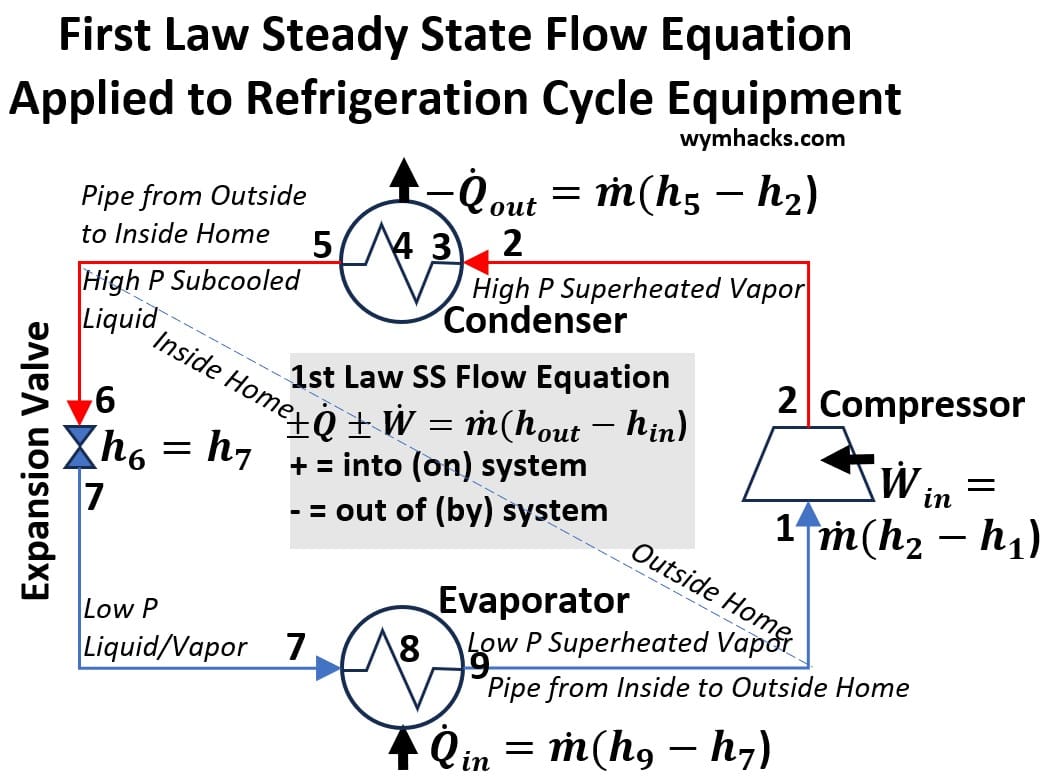
The 1st law applied to a refrigeration loop is shown in the picture below.
Schematic: First Law Steady State Flow Equation Applied to Refrigeration Cycle Equipment
Let’s re-write equation (9) as
(10) Q̇ – Ẇs = ṁ(hexit – hentry) ; 1st Law Steady State Flow Equation; Negligible External KE and PE)
- “Steady State” means that if you zoom in on any single, specific point in the system, the properties at that exact location do not change over time.
- Q̇ (Heat Transfer Rate): The amount of heat transferred per unit of time (e.g., Watts, BTU/hr).
- Ẇs (Power / Work Rate): The amount of external work done per unit of time (e.g., Horsepower, kW).
- Generally (historically) described as “Shaft” work (delivered by a piston for example) but actually includes other external energy work as well.
- Shaft work Ẇs is the total rate of net external energy—such as mechanical rotation, moving pistons, or electrical power—that crosses the system boundary to do useful work on or by the fluid.
- It excludes the fluid’s own pressure-volume flow work, which is already accounted for inside the enthalpy term.
- ṁ (Mass Flow Rate): The amount of mass flowing through the component per unit of time (e.g., kg/s, lb/min).
- h (Specific Enthalpy): This is energy per unit of mass (e.g., kJ/kg or btu/lb).
- lower case h implies this per mass basis (often described as the “Specific Enthalpy”).
It does not have a dot because it is a property of the fluid itself, not a flow rate of energy.
Because the fluid is moving, Enthalpy acts as an “energy tracker.”
It accounts for both the internal energy of the fluid and the “flow work” required to push the fluid into the machine.
Here is the 1st law flow equation 10 applied to the four stages of the cycle (you can refer to the picture above as needed):
1. The Evaporator (Heat Addition)
The refrigerant absorbs heat at a constant pressure.
Since the system does no work (Ẇ = 0), the heat added rate is equal to the mass flow rate multiplied by the change in enthalpy.
(11) Q̇in = ṁ(h9 – h7) ; Evaporator in the Vapor Compression Cycle
2. The Compressor (Work Input)
The compressor squeezes the vapor.
Assuming the process is adiabatic (Q̇ = 0), the work input rate required from the motor is equal to the mass flow rate multiplied by the change in enthalpy.
(12) Ẇin = ṁ(h2 – h1) ; Compressor in the Vapor Compression Cycle
3. The Condenser (Heat Rejection)
The high-pressure vapor releases heat to the environment at constant pressure.
With no work done by the system (Ẇ = 0), the heat rejected rate is the mass flow rate multiplied by the enthalpy lost by the refrigerant.
(13) -Q̇out = ṁ(h5 – h2) or Q̇out = ṁ(h2 – h5) ; Condenser in the Vapor Compression Cycle
note: we are sticking to the convention here so we put a negative sign in front of the heat rate term Q (or we flip or switch the H terms).
4. The Expansion Valve (Pressure Drop)
The liquid passes through a small orifice, dropping in pressure.
This is a “throttling” process where no heat is transferred and no work is performed (Q̇ = 0, Ẇ = 0).
Therefore, the enthalpy before the valve must equal the enthalpy after the valve (isenthalpic).
0 = ṁ(H7 – H6)
(14) h7 = h6 ; Expansion Valve in the Vapor Compression Cycle
By tracking the enthalpy (H) at every stage, you successfully map the energy budget of the entire refrigeration system.
External kinetic and potential energy terms are not always negligible
For our refrigeration loop, the external KE and PE terms are negligible (approximately 0).
But, depending on the system and the equipment, these terms wont always be negligible.
Examples:
1. High KE: Nozzles and Diffusers
2. High KE: Design of High velocity turbines
3. High KE: Rocket and jet engines
4. High PE: Hydroelectric power plants
5. High PE: Deep well pumps
6. High PE: Long distance pipelines
Now we understand the relationships among heat, enthalpy and work in refrigeration cycles.
Enthalpy (H or h) in particular is a very useful term.
We will see in the next section how it can be used with temperature to describe the phase behavior of substances.
Temperature-Enthalpy (T-h) Charts
While the P-T curve identifies exactly when a refrigerant changes phase, it lacks a critical variable in refrigeration physics: energy.
Knowing the boiling point at a given pressure does not tell us how much heat must be absorbed to convert that liquid into vapor.
- Quantifying this heat transfer is essential for system design and analysis.
- To observe this energy shift in isolation, we must hold the pressure constant and track how temperature responds as heat is added.
This introduces our second foundational tool: the Temperature-Enthalpy (T-H) or (T-h) chart.
This is where our newly introduced concept of enthalpy (H) becomes practical.
By tracking enthalpy, this tool allows us to map exactly how heat translates into measurable energy changes during a phase change—whether the refrigerant is a pure liquid, a pure vapor, or a saturated mixture of bot
T-h Chart for Water
Consider the following temperature-enthalpy chart for water which beautifully illustrates the concepts of phase change, sensible heat, and latent heat.
Chart: T-h Chart for Water
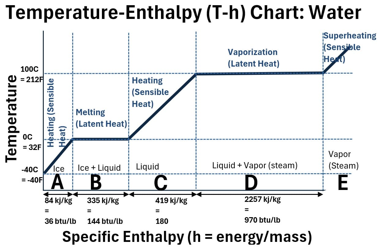
The chart shows (moving from left to right), the temperature of water (at atmospheric pressure) as it transforms from ice (A) to liquid (B, C, D) to vapor (D, E).
- The chart shows temperature (y axis) plotted against specific enthalpy (y axis)
- Specific Enthalpy is Enthalpy (h) expressed as energy/mass (eg. kilo joules/kilogram or British Thermal Units/pound mass)
- The T-h line represented in this chart is an isobaric line (constant pressure….in this example we show it for water at atmospheric pressure)
- As we move from left to right on the y axis heat Q is being added to the water.
- The enthalpy H represents the total energy content of the water, resulting from this heat addition
- H = U + PV (see Appendix 1 for how we derived this) or on a per mass or specific basis h = u = Pv
- For a constant pressure process (which is the case for the line in the chart) the change in enthalpy will equal the amount of heat added.
ΔH = Qconstant P (see Appendix 1 for how we derived this)
T-h Behavior of Water
As we move from left to right on the T-h chart for water, let’s describe what is happening in terms of h = u + Pv.
Remember that u is the internal energy which is the sum of all the internal kinetic and potential energies of the substance. (lower case u means on a per mass or specific basis_.
A. Heating Solid Ice (Sensible Heat)
- The Path: A steep, upward-sloping line starting from sub-zero temperatures up to 0 degrees Celsius (C) = 32 degrees Fahrenheit (F)
- Heat Type: Sensible Heat (heat that causes a measurable change in temperature).
- u and Pv Changes: Virtually all added energy goes into increasing the kinetic energy of the crystalline lattice, causing u to increase sharply.
- Because ice expands only minutely with temperature, the volume change (Δv) is negligible.
- Therefore, Pv remains nearly constant, and Δh ≈ Δu.
B. Melting: Ice to Liquid Water (Latent Heat of Fusion)
- The Path: A horizontal plateau at 0 C. Temperature remains constant while enthalpy increases.
- Heat Type: Latent Heat (heat that changes the phase without changing the temperature).
- u and Pv Changes:
- Energy is used entirely to break the rigid intermolecular hydrogen bonds of the ice lattice. This represents a large increase in potential internal energy (u).
- Water is a unique anomaly here: ice contracts slightly when it melts into liquid water (Δv < 0).
- This means Pv decreases slightly, but the magnitude is so small compared to the massive jump in u that Δh ≈ Δu
C. Heating Liquid Water (Sensible Heat)
- The water here (before it reaches its boiling point) is often described as sub-cooled liquid.
- The Path: Another upward-sloping line from 0 C up to the boiling point (100 C at atm pressure). The slope is different from ice because liquid water has a higher specific heat capacity.
- Heat Type: Sensible Heat.
- u and Pv Changes:
- Added energy increases the thermal molecular motion, causing u to steadily increase.
- Liquid water expands slightly, but at typical pressures, ΔPv is negligible. Enthalpy rise is driven almost entirely by ΔU.
D. Boiling: Liquid Water to Vapor (Latent Heat of Vaporization)
- The Path: A long, perfectly horizontal plateau at the boiling temperature. This is typically the longest segment on the diagram.
- Heat Type: Latent Heat.
- U and PV Changes:
- Δu increases significantly: Energy is heavily consumed to completely overcome the attractive intermolecular forces pulling the liquid molecules together, separating them into a chaotic gaseous state.
- ΔPv increases dramatically: Unlike the previous steps, the fluid undergoes a massive volumetric expansion (Δv >> 0). At constant pressure, the system must perform significant expansion work against the environment.
- Therefore, the Latent Heat of Vaporization (Δh) is split: the majority goes into increasing internal energy (Δu), but a substantial portion is dedicated to the boundary work (Δ(v)).
E. Heating Steam (Sensible Heat)
- As the last liquid drop vanishes (at the start of E in the chart above), the dry gas (often called superheated gas or vapor) temperature starts to increase.
- The Path: An upward-sloping line extending from the right side of the boiling plateau into the superheated vapor region.
- Heat Type: Sensible Heat.
- u and Pv Changes:
- u increases as the gas molecules speed up and gain kinetic energy.
- If held at constant pressure, the gas expands significantly with temperature (v ∝ T), meaning Pv increases noticeably alongside u, with both terms contributing to the rise in h.
You shouldn’t be surprised that many substances follow the same general shape on a T-h diagram.
The one we are interested in (for a typical HVAC system of a house in the USA at least) is R410A (note that starting in 2025 in the USA, new units are required to use more environmentally friendly refrigerants like R454B and R32. )
T-h Chart for Typical (USA) Home HVAC Refrigerant R410A
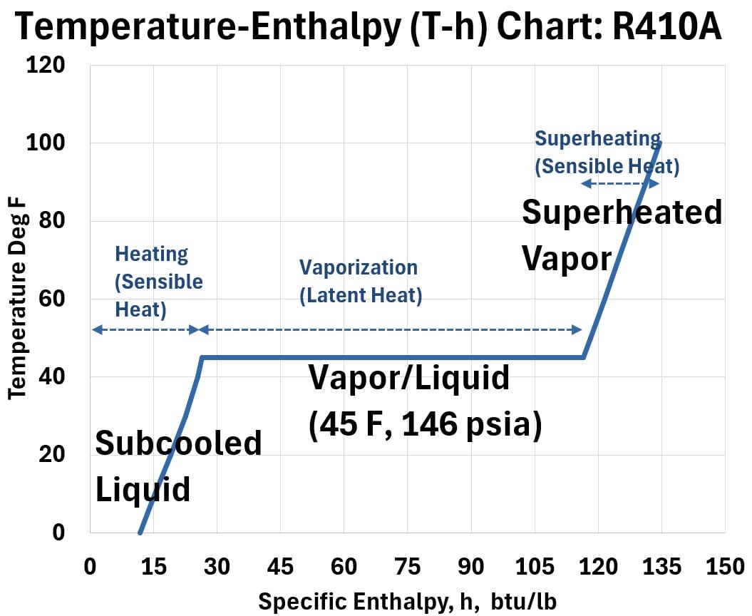
In a refrigeration cycle, the refrigerant will cycle through this phase range (from subcooled vapor, to boiling point mixture, to superheat vapor).
Regarding Current Trends in HVAC Refrigerant
Worldwide, R410A is being phased out of new residential HVAC systems and replaced by lower-GWP alternatives like R32 and R454B to comply with international climate agreements.
While R410A has a high Global Warming Potential of over 2,000, these newer options reduce environmental impact by 70% to 75% while maintaining similar heating and cooling efficiencies.
Summary
- Sensible Heat: Energy that changes temperature but not the state (slope on a graph).
- Latent Heat: Energy that changes the state but not the temperature (the “flat” parts of the graph where phase change occurs).
- The Visualization: Use the T-h diagram to show how a refrigerant “soaks up” energy—first by rising in temperature (sensible), then by boiling (latent)
We now have all the information needed to describe the Mollier Chart (a Pressure – Enthalpy Diagram or Chart).
Pressure-Enthalpy Charts
Synthesizing the Data: The Mollier Diagram
We’ve seen that the T-H chart provides a clear view of the energy absorbed during the phase change plateau.
However, it comes with a major limitation: the entire chart represents only one single pressure level.
Because a working refrigeration cycle constantly changes pressures—compressing vapor to a high-pressure condenser and expanding liquid down to a low-pressure evaporator—relying solely on T-H charts would require analyzing an impractical stack of individual diagrams for every operating pressure.
The Mollier diagram solves this by combining the core strengths of P-T and T-H into a single graphic.
A Mollier Pressure-Enthalpy (P-H or P-h) diagram is a thermodynamic map used to track how a fluid changes state and moves energy.
By plotting pressure on the vertical axis against the enthalpy on the horizontal axis, it simplifies complex refrigeration, heat pump, and gas liquefaction cycles into a visual, geometric loop.
Here are the major features of the chart: Refer to the chart below as you read the descriptive text below it.
Chart: Pressure-Enthalpy, P-h Mollier Chart
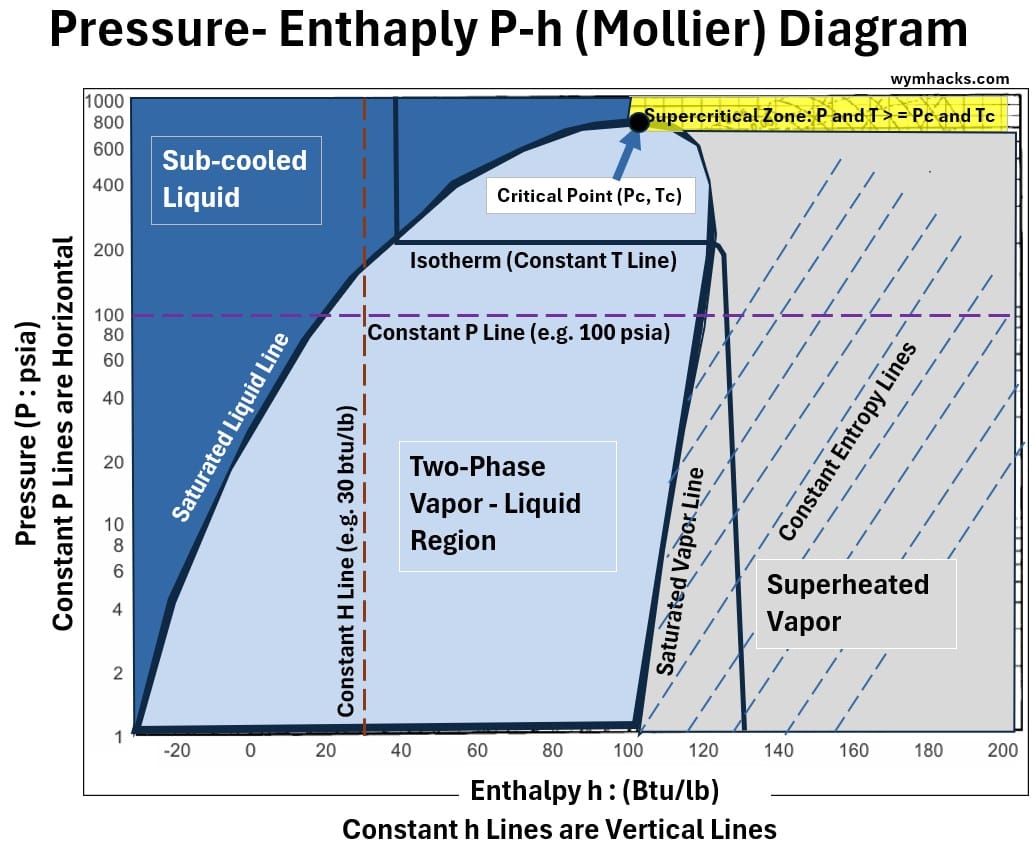
The Saturation Dome (Phase Zones)
The inverted, thumb-shaped curve (envelope) in the center divides the fluid into three states:
- Left of the Dome: Subcooled Liquid (100% liquid, below boiling point).
- Inside the Dome: Two-Phase Mixture (liquid and vapor actively boiling or condensing together).
- Right of the Dome: Superheated Vapor (100% dry gas, heated past boiling point i.e. superheated).
- The Slopes: The left boundary is the Saturated Liquid Line; the right boundary is the Saturated Vapor Line. They meet at the Critical Point at the very top.
Core Axes
- Vertical Axis (Pressure, P): Uses a logarithmic scale to compress massive pressure differences (like high-pressure condensers vs. low-pressure evaporators) onto one page.
- Horizontal Axis (Enthalpy, H): Uses a linear scale to measure total heat energy (kJ/kg).
- Moving right means heat is added; moving left means heat is removed.
The Five Grid Lines
To plot a cycle, you follow five distinct types of intersecting lines:
- Constant Pressure (Horizontal): Perfectly flat lines. Evaporation and condensation happen along these.
- Constant Enthalpy (Vertical): Perfectly straight up-and-down lines. Throttling/expansion valves drop straight down these lines.
- Constant Temperature: Drop vertically on the left, run horizontally inside the dome, and curve steeply downward to the right.
- Constant Entropy: Slanted curves moving upward to the right in the vapor zone. Compressors follow these lines (ideally).
- Quality (x): Lines inside the dome marking the percentage of vapor in the mixture (from 0.0 on the left to 1.0 on the right).
Critical Point and Supercritical Zone
The Critical Point and the Supercritical Zone represent the absolute limits of traditional phase changes (boiling and condensing).
Here is a succinct breakdown of these two high-pressure features.
The Critical Point
The Critical Point is the exact peak of the saturation dome where the Saturated Liquid Line and the Saturated Vapor Line meet.
- The Physics: At this specific temperature and pressure, the density of the liquid phase becomes exactly equal to the density of the gas phase.
- What happens here: The distinction between liquid and gas vanishes.
- If you heat a fluid exactly at its critical pressure, it transitions from liquid to gas instantly without boiling—there is no latent heat of vaporization , and the width of the dome shrinks to a single point.
Supercritical Zone
The Supercritical Zone is the entire uncharted region above and to the right of the Critical Point, beyond the boundaries of the saturation dome.
The State of Matter: A fluid in this region is called a supercritical fluid.
It is neither a liquid nor a gas, but a hybrid that possesses the high density of a liquid and the low viscosity/diffusivity of a gas.
On the Chart: Because there is no dome in this upper region, a fluid can transition from a high-temperature “gas-like” state to a low-temperature “liquid-like” state along a horizontal pressure line without ever crossing a phase boundary.
No bubbles form, and no condensation line appears.
Real-World Systems Operating in Supercritical Zone
While traditional refrigeration cycles stay safely below the critical point to utilize the cooling power of boiling liquid, modern transcritical systems deliberately operate in the supercritical zone:
CO2 Refrigeration (R744): Carbon dioxide has a very low critical point (31.1C or 88F).
On a warm summer day, a CO2 air conditioner cannot reject heat by condensing gas into a liquid because the ambient air temperature is above the critical point.
Instead, the compressor pumps the CO2 up into the supercritical zone, where a “gas cooler” drops its temperature without condensing it, before dropping it back down under the dome through an expansion valve.
Supercritical Power Plants: Modern steam and CO2 power turbines run at supercritical pressures because the fluid can absorb massive amounts of heat energy without the violent, efficiency-limiting expansion that happens during traditional boiling.
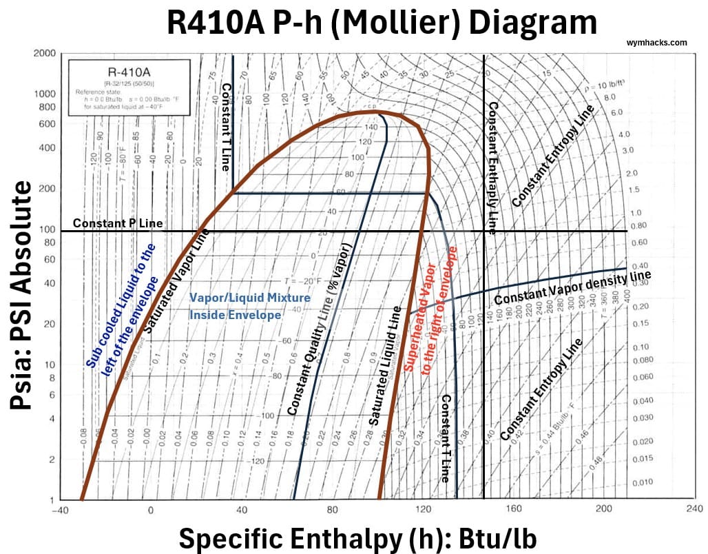
R410A Mollier Chart
Each refrigerant will have its own specific Mollier chart.
The chart below is the Mollier chart (diagram) for R410A, the refrigerant currently flowing in my home’s HVAC system.
note: The global phasedown of R410A (driven by regulations like the AIM Act in the U.S. and F-Gas in Europe due to its high Global Warming Potential of 2,088) has pushed the HVAC industry to adopt two primary successors for new residential and light commercial systems: R454B and R32.
- While the newer replacement refrigerants share this same characteristic “thumb-shaped” saturation envelope, their physical dimensions on the grid will vary.
- Specifically, R32 features the largest shift, creating a dome that is significantly wider and sits noticeably higher on the chart than R410A.
- R454B acts as a middle ground, resulting in an envelope that is only slightly higher and slightly wider than the R410A baseline.
R410A Mollier Diagram: Common Home HVAC Refrigerant
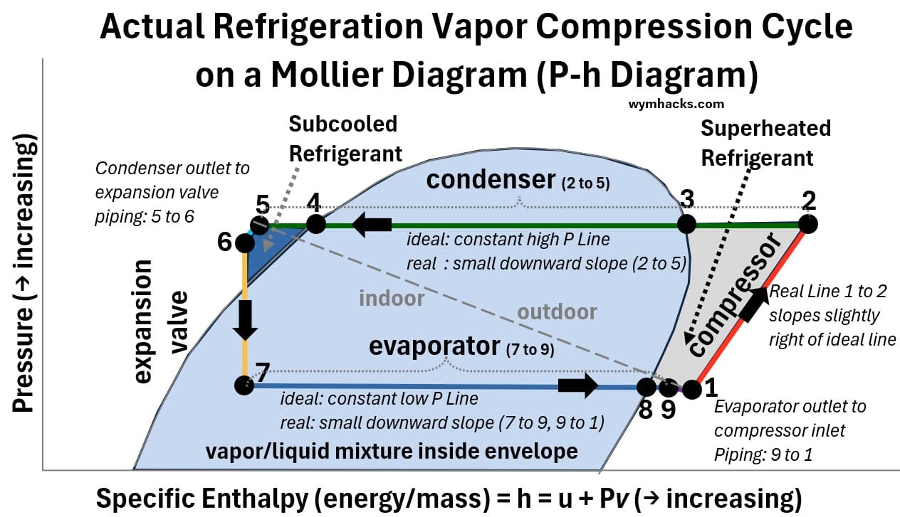
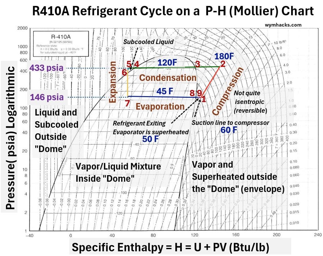
Refrigeration (Vapor Compression) Cycle on a Mollier Diagram
Here is a detailed, step-by-step description of our vapor compression refrigeration cycle as plotted on the Mollier (Pressure-Enthalpy) chart.
A standard Mollier chart places Pressure (P) on the vertical axis and Specific Enthalpy (h) on the horizontal axis.
In this coordinate system, vertical lines represent constant enthalpy (isenthalpic processes) and horizontal lines represent constant pressure (isobaric processes).
Schematic 1: Refrigeration (Vapor Compression) Cycle on a Mollier (P-h) Diagram.
Schematic 2: Refrigeration (Vapor Compression) Cycle on a Generic Mollier (P-h) Diagram With 1st Law Equations

Compression (1 → 2)
Process
Ideal compression of superheated vapor.
For an ideal process
- Q = 0; No heat
- The compression happens so fast that zero heat is lost or gained through the compressor walls to the outside environment.
- It must be reversible: There is absolutely zero internal fluid friction, gas shear, or mechanical turbulence.
- The line from 1 to 2 in the Mollier diagram will move to the right on an isentropic (constant entropy) line
- The line is not quite straight and curves to the right along the constant entropy line for ideal conditions
- An ideal compression stage is described as isentropic because it is assumed to be perfectly insulated and frictionless, meaning no heat is exchanged and no internal chaos is generated, keeping the refrigerant’s total entropy constant. See Appendix 3 to get clear on the concept of Entropy.
Description
Vapor enters the compressor at suction (1) and leaves at a higher pressure and temperature at discharge (2).
- Work is put into the system (so its sign convention is +)
- No heat transfer, Q = 0 (Adiabatic)
Ẇin = ṁ(h2 – h1) ; First Law Applied to Compressor in the Vapor Compression Cycle
- So, assuming the process is adiabatic (Q̇ = 0), the work input rate required from the motor is equal to the mass flow rate multiplied by the change in enthalpy.
- For an actual (non ideal)compression process, the line 1 to 2 will curve more to the right and will cross over lines of constant entropy.
Condenser De-superheating ,Condensation, and Subcooling (2 → 3 → 4 → 5)
Process
The high-pressure vapor releases heat to the environment at constant pressure.
Description
- High-pressure superheated vapor (2) rejects sensible heat (cools) until it hits the envelope (3) which is the dew point or the saturated vapor line.
- Then it rejects latent heat to become a saturated liquid at the bubble point envelope (4).
- In the final length of condensing coil, the refrigerant is subcooled to point (5)
First Law Equation Application
With no work done by the system (Ẇ = 0), the heat rejected rate is the mass flow rate multiplied by the enthalpy lost by the refrigerant.
-Q̇out = ṁ(h5 – h2) or Q̇out = ṁ(h2 – h5) ; Condenser in the Vapor Compression Cycle
note: we are sticking to the convention here so we put a negative sign in front of the heat rate term Q (or we flip or switch the H terms).
Liquid Line to Inside Unit Expansion Valve (5→6)
Process
The liquid line carrying condensed subcooled refrigerant to the inside unit TXV valve/evaporator system.
Description
This line is the smaller of the two copper pipes connecting the split system, and its job is to carry warm, high-pressure liquid refrigerant from the outdoor condenser to the indoor expansion valve (TXV).
- In standard installations, the liquid line is left as bare copper.
- Because the liquid refrigerant inside is warmer than the conditioned indoor air (unless it is in a Houston attic!), leaving the pipe exposed allows it to safely reject a little extra heat.
- This helps maintain or even increase the refrigerant’s subcooling without any risk of the pipe sweating.
The Hot Attic Exception (e.g., Houston or other hot climate cities): When the indoor unit is located in a scorching environment like an unconditioned Houston attic—where summer temperatures easily soar past 130F—the rules change.
Because the attic air is now significantly hotter than the refrigerant, a bare liquid line would absorb that extreme ambient heat.
This bakes the pipe, destroys the subcooling, and causes the refrigerant to flash into a gas before reaching the TXV.
Therefore, the portion of the liquid line running through a hot attic must be fully insulated to shield it from the heat.
The Impact of Pressure Drop (Line Loss)
- As the refrigerant travels through the liquid line, it naturally experiences a small loss in pressure (line loss) caused by friction against the copper walls, elbows, and fighting gravity to travel upward.
- This pressure drop lowers the refrigerant’s boiling point.
- If the system doesn’t have enough subcooling to act as a cushion, this natural drop in pressure—combined with any attic heat gain—will cause the liquid to start boiling prematurely. Properly insulating the liquid line in the attic ensures that despite the inevitable line loss, the refrigerant arrives at the expansion valve as a pure, solid liquid.
On the Mollier chart I’ve drawn a short line from 5 to 6…not drawn to scale (decreasing in pressure i.e. downward direction) and dropping in temperature (i.e. left direction)
Liquid Line Filter Drier
In a standard residential split system, the filter drier is located on the liquid line (the smaller, uninsulated copper line).
- Debris Trapping: It is placed before the metering device (TXV) to catch any copper shavings, flux, or dirt before they can clog the tiny, precise opening of the valve.
- Moisture Removal: The filter drier contains a desiccant material that absorbs any water moisture trapped in the system.
- If water moisture reaches the TXV, it can freeze instantly, blocking the refrigerant flow completely.
- It looks like a small metal cylinder or “bullet” welded directly into the thin copper line.
- Depending on who installed your system, you will find it in one of two places:
- Outside: Right next to the outdoor condenser unit before the liquid line heads into the house.
- Inside: In the attic, right before the line connects to the TXV cabinet.
Expansion Valve (6 → 7)
Process
Isenthalpic (constant enthalpy) throttling.
Description
High-pressure subcooled liquid (6) drops rapidly in pressure through the expansion valve to point (7), flashing into a low-pressure, low-temperature liquid-vapor mixture.
- The liquid passes through a small orifice, dropping in pressure.
- This is a “throttling” process where no heat is transferred and no work is performed (Q̇ = 0, Ẇ = 0).
- Therefore, the enthalpy before the valve must equal the enthalpy after the valve (isenthalpic).
First Law
0 = ṁ(h7 – h6)
h7 = h6 ; Expansion Valve in the Vapor Compression Cycle
Evaporation & Superheating (7 → 8 → 9)
Process
Isobaric heat absorption.
Description
Two-phase mixture (7) absorbs latent heat in the evaporator until it becomes saturated vapor at the bubble point envelope (8), and then absorbs sensible heat to become superheated vapor (9).
First Law
The refrigerant absorbs heat at a constant pressure.
Since the system does no work (Ẇ = 0), the heat added rate is equal to the mass flow rate multiplied by the change in enthalpy.
Q̇in = ṁ(h9 – h7) ; Evaporator in the Vapor Compression Cycle
Suction (Vapor) Line Return (9 → 1)
Process
Ideally an Isobaric piping run. In reality there will be some line loss (pressure drop).
Description
This line is officially called the suction line (or vapor line).
- It is the larger, insulated copper pipe in the line set.
- Its job is to carry low-pressure, low-temperature superheated vapor from the indoor evaporator coil back to the outdoor compressor.
- Superheated vapor travels from the evaporator outlet (9) back to the compressor suction inlet (1), completing the closed loop.
Insulation (Always 100% Insulated)
Unlike the liquid line, the suction line must be fully insulated along its entire run—both inside the house, through the attic, and all the way to the outdoor unit.
- The refrigerant inside is cold (typically 40 to 50 F}).
- If left uninsulated, the hot Houston attic and outdoor air would rapidly heat the vapor, destroying the compressor’s cooling capacity.
- Furthermore, without insulation, the cold pipe would sweat uncontrollably, rotting out your attic rafters and ceiling drywall.
Pressure Drop (Line Loss)
Just like the liquid line, the suction line experiences a loss in pressure due to friction against the copper walls and bends in the pipe as it travels back outside.
- On a Mollier diagram, this pressure drop moves the point downward.
- A drop in suction pressure means the compressor has to work harder and use more electricity to pump the refrigerant back up to condensing pressure, slightly lowering overall system efficiency.
- Installers keep this line as straight and short as possible to minimize this loss.
- On the Mollier (P-h) diagram, the suction line run sits on the far right side (the superheated vapor zone).
- Because it loses pressure but picks up a tiny bit of safe heat (superheat) on its journey, the line slants downward and slightly to the right before entering the compressor.
Hey, since we are so deep into this now, let’s take a look at a typical refrigeration cycle (with typical pressures and temperatures shown) drawn on a R410A Mollier diagram.
Schematic 3: Refrigeration (Vapor Compression) Cycle on a R410 Mollier (P-h) Diagram.
Major Differences Between an Actual Refrigeration Cycle and an Ideal One
I’ve already mentioned some of the differences between an ideal refrigeration process and a real one but let me recap the main ideas here.
An ideal refrigeration cycle assumes a perfect world with zero friction and instant phase changes.
An actual cycle has to deal with physics and fluid dynamics.
Here are the 4 major deviations you see when you overlay an actual cycle onto an ideal Mollier (P-h) diagram:
1. The Compressor Is Not Isentropic (Slants Right)
- Ideal: Compression is perfectly efficient (isentropic), moving along a constant entropy line.
- Actual: Internal friction and heat generation add extra entropy.
- On the diagram, the compression line slants further to the right, meaning the compressor requires more work (electricity) and discharges the vapor at a much higher temperature than ideal.
2. Pressure Drops in the Lines (Slants Downward)
- Ideal: The condenser and evaporator operate at perfectly constant pressures (perfectly horizontal lines).
- Actual: Friction inside the copper tubing, bends, and components (like the filter drier) causes pressure drops.
- The high-pressure side slants downward as it moves through the condenser and liquid line.
- The low-pressure side slants downward as it moves through the evaporator and suction line.
3. Subcooling and Superheating are Required (Extends Past the Dome)
- Ideal: Refrigerant leaves the condenser as a 100% saturated liquid and leaves the evaporator as a 100% saturated vapor (ending exactly on the dome walls).
- Actual: To protect the hardware, the cycle intentionally pushes past the dome.
- Subcooling pushes the condenser exit line further to the left of the dome to ensure pure liquid hits the TXV.
- Superheating pushes the evaporator exit line further to the right of the dome to ensure no liquid slugs the compressor.
4. The Expansion Valve is Not Perfectly Isenthalpic (Minor Drift)
- Ideal: The expansion valve drops pressure instantly with zero heat exchange, moving perfectly straight down (constant enthalpy).
- Actual: There is a tiny amount of friction and minor heat transfer through the valve body, causing a very slight deviation from a perfectly vertical line, though it is usually treated as vertical for practical troubleshooting.
These Deviations Might not seem Obvious or Important Due to Difference in Magnitude relative to Other Changes
In a normally functioning system, pressure drops are very small compared to the overall scale of the cycle.
- If you look at the entire Mollier diagram for a standard residential AC, the big vertical jumps (the compressor pumping the pressure way up and the TXV dropping the pressure way down) span hundreds of PSI.
- In contrast:
The pressure drop across the liquid line might only be 3 to 5 PSI
The pressure drop across the suction line might only be 1 to 2 PSI
On the diagram, these look like tiny, almost imperceptible downward slants.
When Those “Small” Pressure Drops Become a Big Problem
Even if a pressure drop looks like a “tiny slant” on the giant scale of the Mollier diagram, that doesn’t mean it’s trivial.
In fact, a “slight” change in pressure matters immensely because of a critical rule of refrigeration physics: pressure dictates temperature.
When you change the pressure of a saturated refrigerant even a little bit, you instantly change its boiling/condensing temperature.
Here is exactly how those “slight” changes break your system when mapped to your baseline cycle of 146 psia on the low side and 433 psia on the high side:
1. On the Low Side (Suction Line): Every PSI Costs You Cooling
On the suction line running from your attic to the outdoor unit, a drop of just a few PSI looks totally flat on a Mollier chart.
But look at what it does to the temperature of the R410A:
The Target: Your system is designed to boil refrigerant in the evaporator at 146 psia, which gives you that exact, target evaporator coil temperature of 45F.
Line Loss: Friction, sharp elbows, or a slight dent in that copper suction pipe creates a pressure drop of just 10 psi as the gas travels outside, pulling the pressure down to 136 psia before it reaches the compressor suction.
The Impact: Dropping to 136 psia instantly drags your saturation temperature down from 45F down to 41F.
While a 4F drop seems minor, you have just forced the compressor to work harder to pull a lower pressure, sacrificing efficiency.
If that suction line restriction gets slightly worse and drops another 20 psi down to 116 psia, your saturation temperature plummets to 32F.
That minor pressure loss will freeze your indoor system into a solid block of ice, cutting off all airflow to your house.
2. On the High Side (Liquid Line): Losing Your Cushion
On your high side, the condenser converts the hot gas into liquid at 433 psia, establishing your condensing saturation temperature of exactly 120F.
If your outdoor unit subcools that liquid by 10F, the liquid entering the pipe is a solid stream at 110 F.
That 10 F difference is your safety buffer.
The Line Loss: As that high-pressure liquid fights friction and gravity to climb straight up into your hot Houston attic, it suffers a line drop of 20 psi, dropping the line pressure from 433 psia down to 413 psia.
The Trap: At 413 psia, the boiling point of R410A drops from 120 F to 115 F.
Just like that, your subcooling safety cushion was slashed from 10F down to just 5 F solely from a minor pressure drop.
If you combine that pressure loss with a bare, uninsulated copper pipe soaking up heat from a 140 F attic, your remaining 5 F buffer hits zero.
The liquid reaches its bubble point and instantly flashes into vapor bubbles right inside the pipe, choking your TXV.
The Verdict
On the overall Mollier diagram, these lines look almost horizontal because the compressor is slamming the refrigerant up a massive vertical ladder from 146 psia all the way to 433 psia (a span of nearly 300 psi).
But inside the actual components, refrigeration is a game of inches.
A slight, unexpected pressure drop won’t change the macroscopic shape of the Mollier diagram, but it completely alters the phase state of the refrigerant inside your pipes, converting a perfectly running AC into a costly service call.
We’ve covered a lot of ground.
You should now have a solid understanding of refrigeration cycles how we can interpret them on Pressure-Enthalpy charts.
Its now time to introduce the heat pump concept, which utilizes a refrigeration cycle to not only produce cooling but also heating (by essentially reversing the refrigerant flow).
Ductless Mini-Split Cooling / Heating Systems (Heat Pumps)
While the North American standard has long relied on burning fossil fuels or drawing electric currents to provide home heating, most of the rest of the world uses a different design concept.
Enter the ductless mini-split—a system frequently referred to in consumer markets as a “heat pump.”
Schematic: Mini Split, Ductless Heat Pump (Cooling / Heating System)
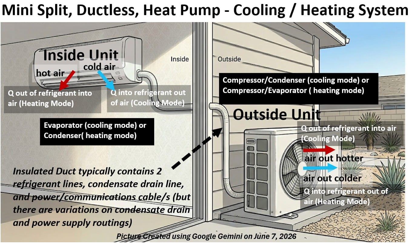
Why Ductless?
The global prevalence of these systems comes down to a mix of architectural reality and energy economics.
- In the United States, cheap land and post-war construction booms allowed houses to be built with dedicated space for massive networks of sheet-metal ductwork.
- Outside the US, however, homes are often older, built with solid stone or concrete, and subject to much higher electricity rates.
- Retrofitting ducts into these structures is structurally impossible and economically impractical.
Mini-splits solve this problem cleanly:
- they completely eliminate the ductwork, utilizing thin, flexible refrigerant lines to connect individual indoor unit (or units) to a single outdoor unit.
Heat Pump?
This design shift highlights a common point of industry confusion.
- From a physics standpoint, a traditional US split central air conditioner is already a heat pump; it shares 90% of the same mechanical DNA, featuring the exact same compressor, expansion valve, and coils.
- The only catch is that it is a cooling-only heat pump (the heating is done by external means; by burning fuel or electrically heating an element)
- Because it lacks a way to reverse its cycle, it is physically locked into moving heat in just one direction: out of your house.
- Furthermore, the term “pumping” is a bit of a misnomer.
- Heat isn’t being mechanically pushed against its will.
- Heat always moves downhill from a high temperature reservoir to a low temperature reservoir (see why in Appendix 3).
- Instead, the system uses its compressor (which effectively is a pump that increases pressure) and expansion valve (a throttling pressure letdown device) to manipulate refrigerant pressures (and therefore temperatures as well).
- Because heat naturally flows from hot to cold, the system simply coaxes thermal energy into transferring where we want it to go.
- But you can see how the word “pump”, used less rigorously, can help us conceptualize heat being rejected from or added to the home.
- Heat isn’t being mechanically pushed against its will.
A mini-split earns its unique reputation because it unlocks this pressure-manipulation process to work in both directions, while delivering that thermal energy directly to the room without duct losses.
For the sake of simplicity, we are describing a standard single-room (zone) installation—though these systems easily scale up to multi-zone designs.
- Note that in a multi zone design , each zone would have its dedicated conduit (for refrigerant and electrical)
Regardless of the scale, the core mechanical principle remains exactly the same.
- Instead of relying on a dedicated furnace to generate brand-new heat, a mini-split introduces the reversing valve.
- In the summer,
- the system provides cooling as we have already described for air cooling (ac) vapor compression systems
- i.e. the inside evaporator absorbs heat and outside condenser rejects heat.
- In the winter, through use of clever technology (electronics, three way valves, electronic expansion valve)
- the outside unit heat exchanger becomes the heat absorbing evaporator and the inside unit becomes the heat producing condenser.
- the functions of the inside and outside heat exchangers are flipped.
- i.e. the outside unit condenser becomes the outside evaporator;
- The system drops the outdoor coil’s temperature well below the cold ambient air, forcing environmental heat to transfer into the refrigerant.
- i.e. the inside unit evaporator becomes the inside condenser
- The compressor tightly packs the refrigerant to raise its temperature even higher, allowing the indoor coil to reject that harvested environmental heat straight into your living room.
What I just described above can be depicted nicely in the schematic below where you can follow the refrigerant path in cooling mode (blue) or heating mode (red).
Schematic – Heat Pump Refrigerant Flow – Heating Mode and Cooling Mode
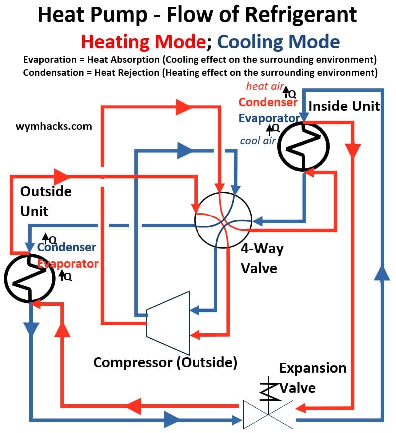
Let’s take a more detailed look at how these “heat pumps” operate.
Heat Pump Operation
Cooling Mode
Schematic – Mini Split Heat Pump – Cooling Mode
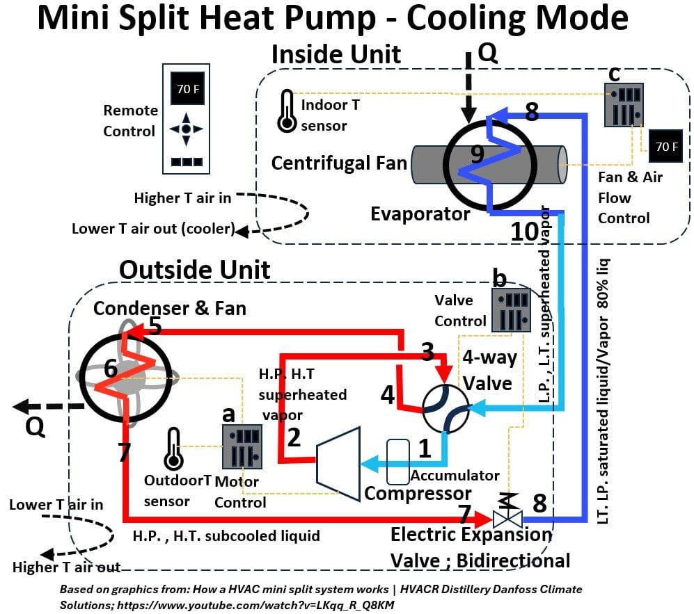
In cooling mode, a mini-ductless heat pump operates as a standard air conditioner,
- moving heat from the indoors to the outdoors using a closed-loop refrigeration cycle.
Here is a step-by-step breakdown of the flow path.
The Cooling Cycle Flow Path
Suction & Compression (1–2)
- Low-pressure, gaseous refrigerant passes through the accumulator to catch any remaining liquid,
- enters the compressor suction port, and is
- compressed into a high-pressure, high-temperature vapor at the compressor discharge.
Routing to Condenser (3–5)
This hot vapor enters the 4-way reversing valve, which routes it directly to the inlet of the outdoor condenser coil.
Heat Rejection (6)
As it flows through the condenser,
- the outdoor fan blows ambient air across the coil,
- causing the refrigerant to reject heat and condense into a high-pressure liquid.
Expansion (7–8)
The liquid leaves the condenser outlet and enters the Electronic Expansion Valve (EEV).
- The EEV drops the refrigerant’s pressure and temperature, turning it into a cold, low-pressure liquid/vapor mix.
Heat Absorption (9)
This cold refrigerant enters the indoor evaporator coil.
- The indoor blower passes warm room air over the coil;
- the refrigerant absorbs this heat, cooling the space and
- boiling the refrigerant into a low-pressure gas.
Return Loop (10)
The gaseous refrigerant
- leaves the evaporator,
- travels back through the 4-way valve, and
- returns to the accumulator to repeat the cycle.
Summary of Component Roles in Cooling Mode
- Outdoor Coil (heat exchanger) : Acts as the condenser (rejects heat).
- Indoor Coil (heat exchanger) : Acts as the evaporator (absorbs heat/cools the room).
- 4-Way Valve: Remains de-energized (typically) to lock the refrigerant flow into this specific cooling path.
Cooling Cycle Control Systems & Logic
In addition to the refrigerant path, the system relies on three dedicated controllers to manage capacity, efficiency, and user comfort:
Outdoor Motor Controller (a)
This controller manages system capacity.
- By monitoring the outdoor temperature sensor, it calculates the thermal load on the system.
- It then adjusts the speed of the compressor (via an inverter drive) to match the cooling demand precisely, rather than cycling drastically on and off.
Outdoor Valve Controller (b)
This manages the physical state of the refrigerant.
- It commands the 4-way valve to stay in cooling mode and constantly adjusts the Electronic Expansion Valve (EEV).
- By monitoring system pressures and temperatures, it opens or closes the EEV to maintain the ideal refrigerant flow and superheat.
Indoor Fan & Airflow Controller (c)
This is the primary comfort interface.
- It compares the thermostat setting from your remote control against the actual room condition via the indoor temperature sensor.
- It then modulates the indoor fan speed and airflow louvers to distribute cool air evenly and maintain the target temperature.
Heating Mode
Schematic – Mini Split Heat Pump – Heating Mode
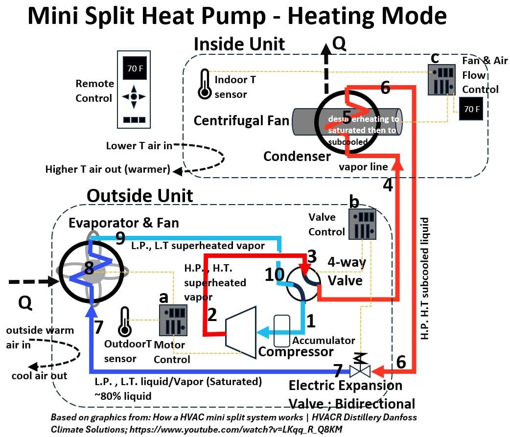
The Heating Cycle Flow Path
In heating mode, the 4-way valve reverses the flow of refrigerant, effectively swapping the roles of the indoor and outdoor coils so the system can capture heat from the outside air and move it indoors.
Compression (Steps 1–3)
Low-pressure vapor passes through the accumulator into the compressor suction port.
- The compressor discharges hot, high-pressure vapor (Step 2)
- directly into the inlet of the 4-way reversing valve (Step 3).
Indoor Heat Delivery (Steps 4–5)
The 4-way valve redirects this hot gas indoors to the inside unit coil, which now acts as the condenser.
- As indoor air blows across this coil,
- the refrigerant rejects its heat into the room,
- warming the home and condensing into a high-pressure liquid.
Expansion (Steps 6–7)
The liquid leaves the indoor condenser outlet and travels back to the outdoor unit, entering the Electronic Expansion Valve (EEV).
- The EEV drops the pressure and temperature of the liquid,
- turning it into a very cold, low-pressure mixture.
Outdoor Heat Extraction (Steps 8–9)
This cold refrigerant enters the outside coil, which now acts as the evaporator.
- Because the refrigerant is colder than the outdoor ambient air,
- it absorbs heat from the outside environment,
- causing the refrigerant to boil back into a low-pressure gas.
Return Loop (Step 10)
The gas leaves the evaporator outlet, passes back through the 4-way valve, and returns to the accumulator to restart the heating cycle.
Control Systems & Logic in Heating Mode
While the components and sensors remain physically identical, their control logic adapts specifically for heating:
Outdoor Motor Controller (a)
Monitors the outdoor temperature sensor to anticipate heating demand and potential frost conditions.
- It modulates the speed of the compressor to ramp up heating output when outdoor temperatures drop, ensuring consistent indoor warmth.
Outdoor Valve Controller (b)
Energizes the 4-way valve to shift it into the heating position.
- It dynamically adjusts the EEV to optimize the heat absorption rate at the outdoor coil, preventing liquid refrigerant from slugging the compressor.
- (Note: This controller also initiates defrost cycles when the outdoor coil freezes, temporarily flipping the 4-way valve back to cooling mode to melt ice).
Indoor Fan & Airflow Controller (c)
Compares the indoor temperature sensor against your remote’s thermostat setting.
- In heating mode, it manages the indoor fan speed carefully—often keeping the fan off or low until the indoor coil is sufficiently hot to avoid blowing uncomfortable cold drafts into the room.
- It also adjusts the louvers downward, as warm air naturally rises.
Heating Mode/Cooling Mode Descriptions for Common Residential HVAC Systems
- The US standard split central (ducted) AC system with fossil fuel fired heaters (or electric element heaters)
- The heat pump
- in heating mode: extracting heat from the outdoor air and injecting it into the indoor air to heat it up.
- in cooling mode: extracting heat from the indoor air to cool it and rejecting the heat into the outdoor air.
- This particular heat pump design is called an Air (Source) to Air(Sink) Heat Pump where the terminology assumes heating mode.
But there are many other types and configurations especially if we expand the scope to non residential applications (commercial, industrial, etc.)
Check out the following Appendices for much more:
- Appendix 4 – HVAC Systems (A Broad Listing and Description of 23 Types – Text and Schematics)
- Appendix 5 – HVAC Systems (A Broad Listing and Description of 23 Types – Tabulated)
- Appendix 6 – HVAC Heat Pump Types
- Appendix 7 – HVAC Applications in Different US Climate Zones
The table below is not complete by any means but it gives you some of the common HVAC designs and where the heat is coming from and going to.
Table: Heating/Cooling Mode Descriptions for Common HVAC Types
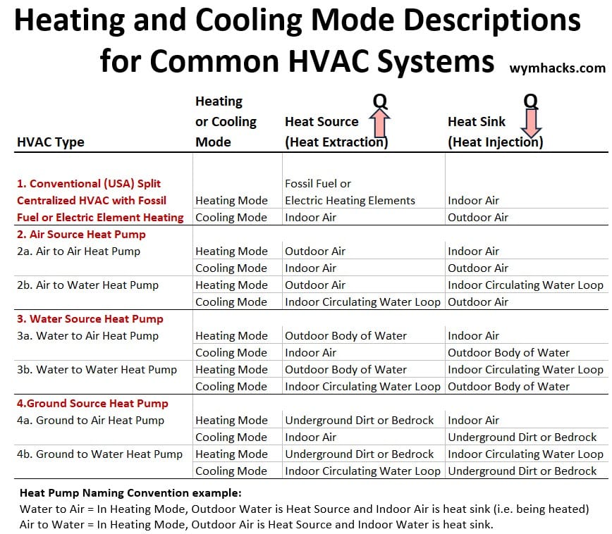
See Appendix 6 for schematics for the different heat pump types.
HVAC Capacity
Up to this point, we’ve covered the mechanics, the thermodynamics, and how a system physically moves heat from inside your home to the great outdoors (and vice versa for heat pumps).
The terminology for how big HVAC systems are can be confusing so let’s discuss capacity (or size) now.
United States Convention is to use “Tons Refrigeration” for Capacity
“Tons” remains the dominant capacity measurement in North America, alongside widespread use in the Middle East and parts of Asia (like India and Singapore) for commercial equipment.
One ton of cooling capacity is the exact amount of heat energy required to completely melt one ton (2,000 lbs) of solid ice over the course of 24 hours.
- It has nothing to do with how much the physical equipment weighs!
- In HVAC terms, one “ton” of cooling capacity is equal to the system’s ability to remove 12,000 BTUs of heat from your home per hour (12,000 BTU/hr).
- Imperial Units: 2000 short tons of ice x 144 BTU/lb latent heat of fusion = 288,000 BTU.
- Delivered evenly over 24 hours gives us 288,000/24 = 12,000 BTU/hr = 1 ton of cooling capacity)
- The latent heat of fusion is the energy required to melt a substance (changing it from a solid to a liquid) without causing any change to its temperature.
Remember the Temperature-Enthalpy chart for Water? The flat line B represents the latent heat of fusion.

- A BTU, or British Thermal Unit, is a standard measurement of heat energy.
- One BTU is the amount of heat required to raise the temperature of one pound mass of liquid water by 1° Fahrenheit (specifically at its maximum density, around 39°F).
- Metric Units: 907.18 kg ice x 334 kJ/Kg = 303,000 KJ
- Delivered in a 24 hour period: 303,000/24 = 12,625 kJ/hr = 12,625 kJ/3600 seconds = 3.507 kJ/s = 3.507 kW = 1 ton of cooling capacity in metric units
- Imperial Units: 2000 short tons of ice x 144 BTU/lb latent heat of fusion = 288,000 BTU.
While early American HVAC pioneers had to convince buyers by comparing their machines to literal tons of melting ice shipped from New England lakes, European engineers approached the problem from the lab.
They skipped the ice phase entirely, measuring cooling power through the lens of thermodynamics—using kilocalories and work—which naturally evolved into the modern Kilowatt standard used globally today.
Example: A Houston, Texas home Using a Split HVAC System.
To give you a real-world example, let’s look at a 2 story home in Houston that has a internal area of about 3,500 ft2 .
- Because we get intense Gulf Coast heat and humidity, this house requires two separate systems:
- a 4-ton unit for the upstairs and
- a 3-ton unit for the downstairs.
So,
- the 3-ton downstairs unit has the capacity to pump 3 x 12,000/hr = 36,000 BTU/hr of heat out of the house,
- while the 4-ton upstairs unit can move 48,000 BTU/hr.
- Why is the upstairs unit larger? Because heat rises, and the roof takes the brunt of that brutal Texas sun!
Example: Sizing a Ductless System for a European Home
Instead of using one massive central system with ductwork, this European home uses small, independent cooling units mounted on the wall in individual rooms.
In Europe, these units are categorized by “Class” numbers, which simply represent how many kilowatts (kW) of cooling power they can put out at maximum speed.
Although units of tons of cooling might not normally be used, remember that 3.507 kW = 1 ton of cooling capacity
1. The Living Room
- About 320 square feet (30m2). It features standard 8-foot ceilings and double-pane windows that get direct afternoon sun.
- To cool a living space with afternoon sun, you need about 70 watts of power per square meter (70 W/m2).
- 30 m2 x 70 W/m2 = 2,100 watts (2.1 kW) of peak cooling needed
- Choose a Class 25 unit (which tops out at 2.5 kW of cooling power).
- 2.5 kW x 3412 BTU/hr/kW = 8,530 BTU/hr = (8,350 BTU/hr)/(12,000 BTU/hr/ton cooling) = .7 tons of cooling
This works because:
- The next size down is a Class 20 unit (2.0 kW), which would struggle to keep the room cool during a harsh summer heatwave.
- Choosing the Class 25 unit gives the room a safe buffer.
- You don’t have to worry about it being too powerful, either.
- On a mild day when the room only needs half that power, the smart, variable-speed motor inside the unit will automatically slow itself down to match the room’s exact needs, saving energy.
2. The Master Bedroom
- About 170 square feet (16 m2). This room is used mostly at night, meaning the unit needs to run quietly while people sleep.
- Bedrooms require less power because they are used when the sun is down. You only need about 60 watts of power per square meter .
- 16 m2 x 60 W/m2 = 960 watts (0.96 kW) of peak cooling needed
- Use a Class 20 unit (which tops out at 2.0 kW of cooling power).
This works because:
- On paper, a 2.0 kW unit is twice as powerful as this small bedroom actually needs.
- However, Class 20 is the absolute smallest size that major manufacturers physically build for the European market.
- Because the motor is designed to automatically scale its power up or down, it handles this perfectly.
HVAC Market Data Observations
The data below comes from the below listed reports (summarized using Google Gemini).
- https://www.marketsandmarkets.com/Market-Reports/hvac-system-market-202111288.html
- https://www.marketsandmarkets.com/Market-Reports/heat-pump-market-153294991.html
See all the graphs and tables I generated from these reports in Appendix 8.
Global Market Summary
The global HVAC industry is fundamentally being rewritten by a massive push toward decarbonization and smart building automation.
- Worldwide, companies and governments are moving away from traditional fossil-fuel heating, causing advanced electric alternatives like heat pumps to rapidly claim a major chunk of the global market share.
- At the same time, the explosion of next-gen commercial needs—like heavy thermal management for data centers running intense AI workloads—is opening up highly lucrative premium niches.
- While high equipment and installation costs remain a hurdle, the industry’s growth is accelerating heavily because of strict environmental laws and massive global subsidy programs like the US Inflation Reduction Act and the EU Green Deal
Residential Market Summary
The residential HVAC market is undergoing a massive shift right now, mostly because extreme weather is forcing everyone to rethink how they heat and cool their homes.
- In places like the US and Europe, people are swapping out their old, clunky systems for smart, tech-heavy setups,
- while across Asia, huge waves of new home construction are driving massive sales.
- On top of that, everyone is trying to ditch traditional gas furnaces for energy-efficient electric heat pumps, especially with governments handing out big tax credits and rebates to help homeowners lower their utility bills.
Regional Share of Global Market
Chart: Global HVAC Market Share (Sales & Volume)
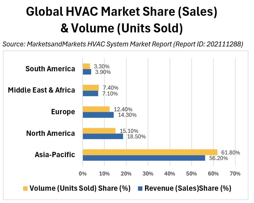
Asia-Pacific (56.20% Rev / 61.80% Vol)
- Why: Driven by massive, rapid urbanization, a booming construction industry, expanding commercial infrastructure, and a surging middle class across nations like China and India.
- Volume vs. Revenue: The volume share is higher than the revenue share because the region relies heavily on cost-efficient, ductless mini-split configurations and benefits from massive localized manufacturing clusters that lower the average hardware cost.
North America (18.50% Rev / 15.10% Vol):
- Why: Driven by rapid infrastructure growth in smart cities, severe weather fluctuations (extreme heat waves and cold snaps), and expanding highly specialized sectors like data centers and healthcare.
- Volume vs. Revenue: The revenue share outpaces volume because North American buildings typically feature large, complex, ducted central systems integrated with high-cost smart tech (IoT/AI controls) and must comply with premium efficiency and environmental standards (like the U.S. Inflation Reduction Act).
Europe (14.30% Rev / 12.40% Vol):
- Why: Driven heavily by aggressive climate goals, strict building safety regulations, and a concerted push for energy security to reduce reliance on fossil fuels.
- Volume vs. Revenue: Revenue is amplified relative to volume due to the widespread transition toward premium, advanced air-to-water hydronic heat pump setups meant to cleanly replace legacy water-boiler systems.
Middle East & Africa (7.10% Rev / 7.40% Vol):
- Why: Driven primarily by expanding commercial properties and persistent high cooling demands in rapid urban expansions.
- Volume vs. Revenue: It sits virtually 1-to-1 with global baseline pricing because the bulk of the market is anchored by standard, cooling-only unitary systems and room air conditioners without complex heating equipment.
South America (3.90% Rev / 3.30% Vol):
- Why: Driven by steady development in key regional urban centers and foundational residential cooling needs.
- Volume vs. Revenue: Revenue is slightly elevated relative to unit volume because the region faces higher localized costs stemming from a heavy structural reliance on imported premium specialized components.
Global Residential vs. Non-Residential (Commercial/Industrial) Market
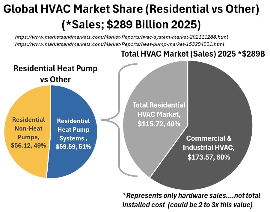
Overall HVAC Market: Split roughly 40% Residential vs. 60% Non-Residential.
While residential has higher unit volume, commercial/industrial projects carry significantly higher per-project engineering and equipment costs.
Residential Market: Heat Pumps vs. Non-Heat Pumps
- Heat Pumps: Account for approximately 51% of residential HVAC spending.
- In regions with proactive climate policies (like the EU and parts of the US), heat pumps represent the majority of new residential heating installations.
- Non-Heat Pumps (Standard AC & Fossil Fuel Heat): Account for 49% of residential market value.
- This is dominated by standard ducted split-system air conditioners in warm climates and traditional gas furnaces in un-subsidized colder zones.
Charts: Global HVAC Heat Pump Market Share
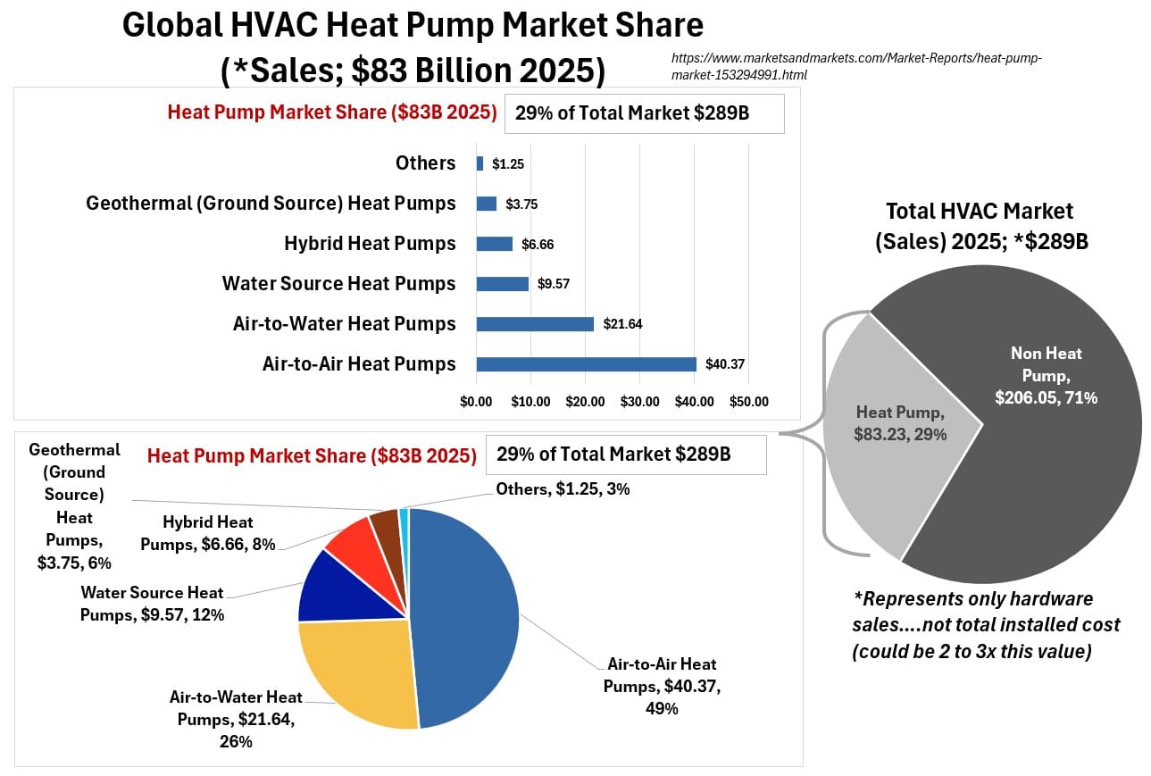
Heat Pump Market Specifically: 71.3% Residential vs. 28.7% Non-Residential.
Heat pump adoption is overwhelmingly driven by the residential sector due to aggressive home electrification subsidies and single-family retrofits.
Global Heat Pump vs. Non-Heat Pump Market Mix
- The Broader HVAC Picture: Heat pumps make up 29% ($83.23B) of the entire global HVAC market ($289B).
- The remaining 71% is non-heat pump technology (standard AC units, chillers, ventilation systems, gas furnaces, and boilers).
- The Dedicated Heating Equipment Segment:
- Within heating equipment alone, heat pumps are the dominant force, accounting for a 50.6% revenue share against traditional gas/oil furnaces and boilers.
Breakdown of Heat Pump Types
- Air-to-Air (Largest Segment): Holds the dominant market share globally.
- It is highly popular due to its lower installation cost and dual capability to provide both forced-air heating and cooling (e.g., standard mini-splits).
- Air-to-Water (Fastest Growing): Expanding rapidly, particularly in Europe.
- These systems heat water for radiant floors or radiators and are heavily favored in fossil-fuel boiler replacement initiatives.
- Other Types (Ground-Source/Geothermal, Water-Source, Hybrid, PVT):
- Represent smaller, niche shares. Geothermal offers the highest efficiency but suffers from high upfront drilling and excavation costs.
Regional Relative Price Factors & Ranking
Chart: Global HVAC Relative Price Factor

Equipment, installation, and compliance costs vary significantly by region:
- North America (Highest Cost):
- Driven by large average property sizes, strict SEER/efficiency mandates, high professional labor/installation rates, and a heavy historical reliance on complex, ducted systems.
- Europe (High-Medium Cost): Driven by high hardware costs for advanced air-to-water hydronic systems and strict environmental/refrigerant compliance, though installation layouts are often more compact than in North America.
- Asia-Pacific (Low-Medium Cost):
- Beneficiary of localized, massive manufacturing economies of scale and a heavy market preference for ductless mini-splits, which are significantly cheaper and less labor-intensive to install.
Appendix 1 – Enthalpy Defined and the 1st Law, Steady State Flow Equation Applied to the Vapor Compression Refrigeration Cycle
Definitions of Enthalpy
The Enthalpy (H) of a system is the sum of its internal energy and energy required to occupy space
or stated a little more explicitly,
The Enthalpy of a system (H) is the total energy contained within it—defined as the sum of its internal energy (U) and the energy required to maintain its volume against its surrounding pressure (PV).
(1.1) H = U + PV
- We often think of ‘Volume’ as something inside a closed tank. But in a system like steam escaping a pot, the volume is simply the space the gas occupies as it moves through the room.
- Even without a tank, the gas has to do work—it has to shove the surrounding air molecules out of the way to exist.
- That ‘shoving’ is the work represented by the PV term in our Enthalpy equation
You will often see enthalpy defined for a process under constant pressure (like a chemical reaction being measured in an open flask).
In any system undergoing a process at constant pressure (an isobaric process), the change in enthalpy (ΔH) is exactly equal to the heat transferred (Q).
(1.2) ΔH = Qconstant P
Pioneers
Rudolf Clausius, The Mechanical Theory of Heat (1867, English edition 1879)
He introduced this concept to describe the total amount of energy associated with a body, which is composed of:
- The heat already present in the body (the internal energy U).
- The heat equivalent of the work that must be expended against external pressure to maintain the body’s volume
He often decomposed the internal energy term U further into:
- Sensible heat: The portion of the internal energy related to the motion of the molecules (what we now associate with kinetic energy and temperature).
- Latent heat / Internal work: The energy expended in overcoming the forces of attraction between the molecules (potential energy of configuration).
J. Willard Gibbs, On the Equilibrium of Heterogeneous Substances (1875–1878):
Gibbs is widely credited with formalizing the function χ = ε + pv (where χ is internal energy, p is pressure, v is volume).
- He referred to this as the “heat function at constant pressure.”
- This is the precise mathematical identity used in engineering today; he proved that for processes at constant pressure, this function acts as the state variable that tracks heat transfer.
Heike Kamerlingh Onnes (early 1900s)
The word “enthalpy” (from the Greek enthalpein, meaning “to warm in”) was proposed by the Dutch physicist Heike Kamerlingh Onnes in the early 1900s.
It was introduced to create a standard term for the function that Gibbs and Clausius had already identified as essential for energy balances.
1st Law of Thermodynamics Equation
Ok, we want to derive the enthalpy relationships we introduced above.
We need to start with the 1st law equation.
The First Law of thermodynamics states that
- Energy is conserved.
- The change in a system’s internal energy
- equals the heat added minus the work done.
There are some assumptions behind these statements so let’s dig a little deeper.
If we start with a process occurring in a simple system/surroundings concept (see picture below), we can depict the 1st law in its most general form.
Note: I suggest you read my post First Law of Thermodynamics for a detailed development of the 1st law equation.
Schematic: First Law of Thermodynamics Closed System
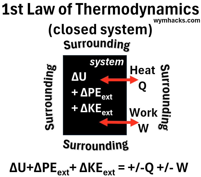
A total energy balance for this process is
(1.3) ΔEtot = ΔΣKEint + ΔΣPEint+ ΔKEext + ΔPEext = +-Qnet+- Wnet (closed system)
where,
- Δ indicates a finite change
- Q and W are the heat and work being added or subtracted from the system.
- Heat Q is energy transferred between objects (or systems) because of a temperature difference (moving from hot to cold).
- Work W is energy transferred by a force acting through a distance (like a piston compressing gas).
- Q and W are energy in transit and have the same unit of energy (in SI units, the Joule).
- i.e. Systems cant contain heat or work. They only show up when energy is crossing a boundary.
- (+) means Q or W is being added to the system (work done to or on system).
- (-) means Q or W is being subtracted from the system (work done by system).
- E tot = Total energy of a substance/object/body
- U = the total Internal Energy = ΣKEint +ΣPEint
- ΣKEint = sum of all Kinetic Energies of the atoms and molecules (internal)
- Kinetic energy is the energy of motion (linear (translational) or rotational).
- ΣPEint = sum of all Potential Energies of the atoms and molecules (internal)
- Potential energy is stored energy that an object possesses due to its position, structure, or state, giving it the potential to do work.
- KEext= kinetic energy of the system as a whole (bulk, external)
- PEext= potential energy of the system as a whole (bulk, external)
Let’s now make some reasonable simplifying assumptions,
- we know the internal energy = ΔU = ΔΣKEint + ΔΣPEint
- also, assume that the system is stationary (KEext negligible) and
- the system PEext is negligible.
So (1.3) becomes
(1.4) ΔU = +-Qnet+- Wnet (closed system)
If we understand that Q and W are the culmination of all the work and heat, then
(1.5) ΔU = +-Q+- W (closed system, negligible external PE and KE)
where +- indicate whether energy from Q and W are either
- increasing (+) the system energy or
- decreasing (-) the system energy
Conventionally (and confusingly in my opinion) you will see (1.5) written as
1.6 ΔU = Q – W (1st law, closed system, negligible external PE and KE)
where
- Q = heat added to the system
- W = Work done by the system
Internal Energy (U) is the total microscopic kinetic and potential energy stored inside the system.
- It is a State function, which means the system doesn’t care how it got its energy; it only cares about its current state.
- Think of Internal Energy like a bank account balance:
- The Account Balance (U): A state function. It is a definite number right now.
- Deposits and Withdrawals (Q and W): Q and W are called Path functions.
- At the end of the day, the bank only tracks the net change in the balance (Delta U or ΔU), regardless of the mix of cash or transfers you used to get there.
Please read these following posts to ensure you understand the above:
Defining H Using a Closed, Isobaric (Constant Pressure) System
We are now going to introduce a really important concept called Enthalpy.
It has a universal definition but it can be derived using the following thought experiment:
Imagine a cylinder filled with an ideal gas, fitted with a frictionless, movable piston.
As we add heat, the gas expands, lifting the piston.
- At the start, the gas is at a lower temperature and volume, and its internal pressure perfectly balances the downward pressure of the atmosphere and the piston’s weight.
- When you add heat, the temperature (T) rises, causing the gas molecules to speed up.
- This creates a momentary pressure spike that pushes the piston upward, increasing the volume (V).
- At the end of the process, the piston comes to rest at a new, higher position.
- Because the piston is free to move, the internal pressure drops back down to exactly match its original value.
- According to the Ideal Gas Law (PV=nRT), since the pressure (P) is constant and the temperature (T) increased, the volume (V) must increase proportionally.
- You finish with a hotter gas taking up more space, but at the exact same pressure as the start.
Picture: Piston Cylinder System Constant Pressure Process
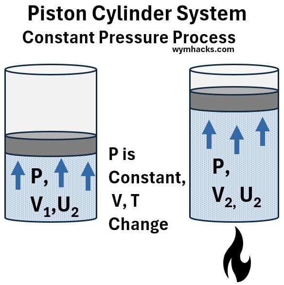
In this closed system, we apply the First Law of Thermodynamics:
1.6 ΔU = Q – W (1st law, closed system, negligible external PE and KE)
or
(1.7) Q = ΔU + W
(1.8) W = Force x distance = F x d = (F)(d)
Let’s convert the work equation into terms of volume and presssure.
- (1.9) Pressure = P = Force/Area = F/A
- (1.10) F = (P)(A)
- Substituting 1.10 into 1.8:
- (1.11) W = (F)(d) = (P)(A)(d)
- but (A)(d) is the piston displacement which equals the cylinder volume change = ΔV.
- Substituting back into (1.11) we get
- (1.12) W = PΔV = P(V2 – V1)….Isobaric Process
Substitute (1.12) into the first law (1.7):
Now, rearrange the terms to group the final state variables together and the initial state variables together:
(1.15) Q = (U2 + PV2 ) – (U1 + PV1 ) Isobaric Process
The specific grouping, (U + PV), appears naturally in our math.
We define this grouping as Enthalpy (H).
(1.16) H = U + PV (Definition of Enthalpy. Always True)
For this specific isobaric process:
(1.17) Qconstant P = H2 – H2= ΔH Isobaric Process
This is equal to equation (1.2) above.
Enthalpy is a Universal State Property
While we used an isobaric process to “discover” Enthalpy, Enthalpy is a universal state property.
It is not restricted to constant-pressure processes, just as Temperature or Pressure are not restricted to them.
Enthalpy (H) is defined for any substance, at any state, as:
(1.16) H = U + PV
Because U, P, and V are state functions (they depend only on the current state of the substance), Enthalpy is also a state function.
- In an Isobaric process: Q = ΔH (a special, simplified case where Enthalpy reveals the heat transfer).
- In ALL other processes: H = U + PV
- It is always a valid property that you can look up in a table for any fluid, regardless of the process path.
The Vapor Compression Refrigeration Cycle
When we shift from a closed piston to a flowing refrigeration cycle, the refrigerant is moving through components at a constant rate.
The vapor compression cycle facilitates heat transfer by circulating a refrigerant through four sequential stages:
- compression,
- condensation,
- expansion, and
- evaporation.
The compressor raises the pressure and temperature of the refrigerant vapor, which then releases its heat to the outside environment in the condenser as it condenses into a high-pressure liquid.
This liquid passes through an expansion valve, where a sharp drop in pressure rapidly cools it, allowing the evaporator to absorb thermal energy from the indoor air.
As the refrigerant turns back into a low-pressure vapor within the evaporator, it returns to the compressor to restart the cycle, effectively cooling the space.
1st Law, Steady State Flow Equation Applied to the Vapor Compression Refrigeration Cycle
This refrigeration cycle can be described by the Steady-State Flow Energy Equation.
I described this in some detail in my post First Law of Thermodynamics (so go there and read it so you can understand equation (1.18) below a little better.)
The equation is:
(1.18) Q̇ – Ẇs = ṁ(hexit – hentry) ; 1st Law Steady State Flow Equation
- “Steady State” means that if you zoom in on any single, specific point in the system, the properties at that exact location do not change over time.
Q̇ (Heat Transfer Rate): The amount of heat transferred per unit of time (e.g., Watts, BTU/hr).
Ẇs (Power / Work Rate): The amount of external work done per unit of time (e.g., Horsepower, kW).
- Generally (historically) described as “Shaft” work (delivered by a piston for example) but actually includes other external energy work as well.
- Shaft work Ẇs is the total rate of net external energy—such as mechanical rotation, moving pistons, or electrical power—that crosses the system boundary to do useful work on or by the fluid.
- It excludes the fluid’s own pressure-volume flow work, which is already accounted for inside the enthalpy term.
ṁ (Mass Flow Rate): The amount of mass flowing through the component per unit of time (e.g., kg/s, lb/min).
h (Specific Enthalpy): This is energy per unit of mass (e.g., kJ/kg or btu/lb).
- lower case h implies this per mass basis (often described as the “Specific Enthalpy”).
It does not have a dot because it is a property of the fluid itself, not a flow rate of energy.
Because the fluid is moving, Enthalpy acts as an “energy tracker.”
It accounts for both the internal energy of the fluid and the “flow work” required to push the fluid into the machine.
Picture: Refrigeration (Vapor Compression) Cycle
Here is the 1st law flow equation applied to the four stages of the cycle (you can refer to the picture above as needed):
1. The Evaporator (Heat Addition)
The refrigerant absorbs heat at a constant pressure.
Since the system does no work (Ẇ = 0), the heat added rate is equal to the mass flow rate multiplied by the change in enthalpy.
(1.19) Q̇in = ṁ(h9 – h7) ; Evaporator in the Vapor Compression Cycle
2. The Compressor (Work Input)
The compressor squeezes the vapor.
Assuming the process is adiabatic (Q̇ = 0), the work input rate required from the motor is equal to the mass flow rate multiplied by the change in enthalpy.
(1.20) Ẇin = ṁ(h2 – h1) ; Compressor in the Vapor Compression Cycle
3. The Condenser (Heat Rejection)
The high-pressure vapor releases heat to the environment at constant pressure.
With no work done by the system (Ẇ = 0), the heat rejected rate is the mass flow rate multiplied by the enthalpy lost by the refrigerant.
(1.21) -Q̇out = ṁ(h5 – h2) or Q̇out = ṁ(h2 – h5) ; Condenser in the Vapor Compression Cycle
note: we are sticking to the convention here so we put a negative sign in front of the heat rate term Q (or we flip or switch the H terms).
4. The Expansion Valve (Pressure Drop)
The liquid passes through a small orifice, dropping in pressure.
This is a “throttling” process where no heat is transferred and no work is performed (Q̇ = 0, Ẇ = 0).
Therefore, the enthalpy before the valve must equal the enthalpy after the valve (isenthalpic).
0 = ṁ(H7 – H6)
(1.22) h7 = h6 ; Expansion Valve in the Vapor Compression Cycle
By tracking the enthalpy (H) at every stage, you successfully map the energy budget of the entire refrigeration system.
Appendix 2 – Pressure, Temperature , and Volume
To master HVAC operations, we have to understand how heat flows into and out of the system (thermodynamics).
And in order to do that we have to first understand some basic units of physical measurement:
- Pressure (P),
- Temperature (T) and
- Volume (V)
Pressure
Pressure is the amount of force exerted perpendicular to a surface, distributed over that surface’s area
Pressure = Force/Area = P = F/A
- It measures the intensity of the push; in fluids, this arises from the continuous, random collisions of particles against a boundary, which is why the resulting force is always directed straight into (perpendicular to) that surface.
- When you sum up billions of random collisions, the “left-right-up-down” components all wash each other out due to symmetry.
- The only component that survives the averaging process is the one pushing straight into the surface.
So, while the individual collisions are random and hit at all angles, the net effect of that bombardment is a force that acts purely perpendicular to the boundary.
That net force is what we measure as pressure.
Gauge vs Absolute Pressure
We are going to describe Mollier Diagrams later on where you will often see the pressure units of measure given in terms of absolute pressure (e.g. psia or lbs per square inch absolute).
But if you are an HVAC technician (or a do it yourselfer) you will often use instruments that measure pressure in terms of gauge (e.g. psig or lbs per square inch gauge).
Gauge pressure is the pressure relative to the ambient pressure.
- Gauge pressure is fundamentally about differential measurement.
- We live in an environment where the atmosphere is constantly pressing down on us, and because that pressure is always present, we rarely need to account for it in daily engineering or mechanical tasks.
- We simply set that baseline to “zero.”
The relationship between absolute pressure Pabs and gauge pressure Pgauge is determined by the ambient atmospheric pressure Patm :
Pabs = Pgauge + Patm
- At sea level, the standard atmospheric reference is 14.7 psi
- Example: a pressure gauge that reads 10 psig is equivalent to 10 + 14.7 = 24.7 psia
- Example: a gauge measuring atmospheric pressure will read 0 gauge (which is 14.7 psia)
All this to say: If you gauge reads X psig, that means it’s equivalent to (X + 14.7) psia.
Chart: psig + atmospheric pressure = psia
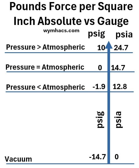
Temperature
Temperature is the quantitative measure of a system’s average kinetic energy.
It acts as a statistical indicator of the total chaotic motion—translation, rotation, and vibration—of the particles that make up a substance.
- Translational motion: the bulk motion of molecules or
- Rotational motion: the rotational movement of molecules or
- Vibrational motion: the vibrational movement of molecules
Units of Measure
In the US we (mostly) use Fahrenheit while most of the rest of the world uses Celsius.
Absolute temperature is a measure of temperature starting from absolute zero, the theoretical coldest possible temperature where molecular motion ceases.
This means absolute scales have no negative values.
- Fahrenheit = F = (C x 9/5) + 32 = (C x 1.8) + 32
- Celsius = C = (F – 32) x 5/9 = (F-32)/1.8
- Celsius to Kelvin: K = C + 273.15
- Kelvin to Celsius: C = K – 273.15
- Fahrenheit to Rankine: R = F + 459.67
- Rankine to Fahrenheit: F = R – 459.67
The Universal Kinetic Energy Equation
The relationship between the average kinetic energy KEavg of a particle and its absolute temperature T is defined by the Equipartition Theorem:
- KEavg : Average kinetic energy per particle.
- T: Absolute temperature (in Kelvin).
- k: The Boltzmann constant (1.38 x 10⁻²³ J/K), which converts temperature to energy units.
- f: The “degrees of freedom,” representing the independent ways a particle can store energy.
A Note on Degrees of Freedom (f)
The value of f represents the independent ways a particle can store energy (translation, rotation, or vibration).
While f is a predictable constant for simple gases, it is difficult to calculate for liquids because molecular crowding “cages” particles, making f a dynamic variable that fluctuates based on the substance’s temperature and pressure.
Volume
Volume (V) is the total amount of three-dimensional space that a substance occupies.
Think of it as the ‘size of the room’ available to the molecules.
While Pressure and Temperature describe the energetic state of a substance—how hard the molecules push and how fast they vibrate—Volume describes its spatial reality.
It dictates how much room the molecules have to move around.
If you keep the same amount of ‘stuff’ (mass) but change the Volume, you change the concentration of the molecules (the density = mass/volume changes).
You cannot fully understand how a substance behaves under pressure or heat unless you know how much space it has to do it in.
Establish that these three are the “state variables”—if you know two, you can usually determine the third for a given mass of refrigerant.
P, v, T are State Variables
For any given mass of refrigerant, pressure (P), specific volume (v), and temperature (T) are the fundamental thermodynamic state variables.
According to the State Postulate, if you know any two of these independent variables, you can mathematically determine the third—along with all other properties of the refrigerant (like enthalpy and entropy).
Appendix 4 – Twenty Three HVAC Types (Text and Schematics)
- Return to HVAC Overview Section
- Return to HVAC type heating cooling mode table
Standard Home Systems (Forced Air)
How Air Conditioning Works – Matt Rittman (shows a basement indoor unit)
These systems use plastic or metal ducts to blow hot or cold air into rooms.
They are what you find in most houses.
1. Traditional Furnace + A/C
Schematic – Typical Home Split Central HVAC System
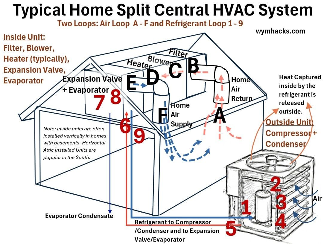
The classic home setup with an indoor furnace and an outdoor A/C.
- Name: Traditional Furnace + A/C
- Ducted / Ductless / Hydronic: Ducted
- Heat Carrier / Heat Absorber in Heating and Cooling Mode:
- Cooling Mode: Refrigerant absorbs heat from indoor air via an evaporator coil and rejects it to the outdoor ambient air via a condenser.
- Heating Mode: No refrigerant heat absorption; combusted fuel or electric resistance heating elements warm the structural air stream directly.
- Heating Technology: Fossil fuel combustion (natural gas, propane, oil) inside a metallic heat exchanger, or heavy-draw electric resistance heating elements.
- Cooling Technology: Standard split-system vapor-compression refrigeration cycle.
- Configuration: Split system consisting of an indoor furnace paired with an cased evaporator coil, connected via field-insulated copper refrigerant lines to a standalone outdoor condensing unit. Air is driven through a single, large central duct network.
- Typical Application: Single-family detached homes, low-rise commercial spaces, and suburban residential developments.
- Main Factors Favoring this Application: Low initial equipment cost, widespread technician familiarity, and highly effective, rapid heating performance in extremely cold northern climates.
2. Standard Heat Pump (Air-Source Split System)
Looks like an A/C but can flip a switch to heat the home too.
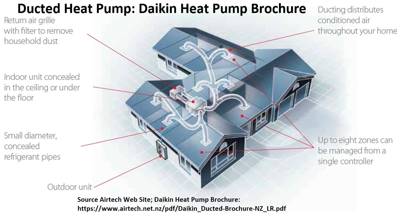
- Name: Standard Split-System Heat Pump
- Ducted / Ductless / Hydronic: Ducted
- Heat Carrier / Heat Absorber in Heating and Cooling Mode:
- Cooling Mode: Refrigerant absorbs heat from indoor air via the indoor evaporator coil and rejects it to the outdoor ambient air via the outdoor condenser coil.
- Heating Mode: Refrigerant absorbs heat from the outdoor ambient air via the outdoor coil (acting as an evaporator) and rejects it to the indoor air via the indoor coil (acting as a condenser).
- Heating Technology: Vapor-compression cycle using a reversing valve to reverse refrigerant flow and extract low-grade thermal energy from outdoor air, usually paired with electric resistance strips for auxiliary/defrost backup.
- Cooling Technology: Standard vapor-compression refrigeration cycle.
- Configuration: Split system consisting of an outdoor unit (compressor, outdoor coil, fan) and an indoor unit (evaporator coil and blower fan, often integrated into an air handler or gas furnace) connected by a pair of insulated copper refrigerant lines. Conditioned air is distributed through a central duct network.
- Typical Application: Single-family detached homes, low-rise apartment buildings, and small standalone commercial offices.
- Main Factors Favoring this Application: Pre-existing central ductwork infrastructure, lower upfront equipment cost compared to multi-zone systems, familiar and simplified maintenance for standard residential technicians, and climates with moderate winter heating needs.
3. Packaged Gas/Electric (Gas Pack / RTU = Roof Top Unit)
RTU Rooftop Units Explained – Engineering Mindset
These are packaged air conditioning units.
They are similar to Air Handling Units AHUs but wont have a chiller (cooling water tower) associated with it for example.
All the parts of a furnace and A/C inside one box outside.
Picture – RTU (Wiki Commons)
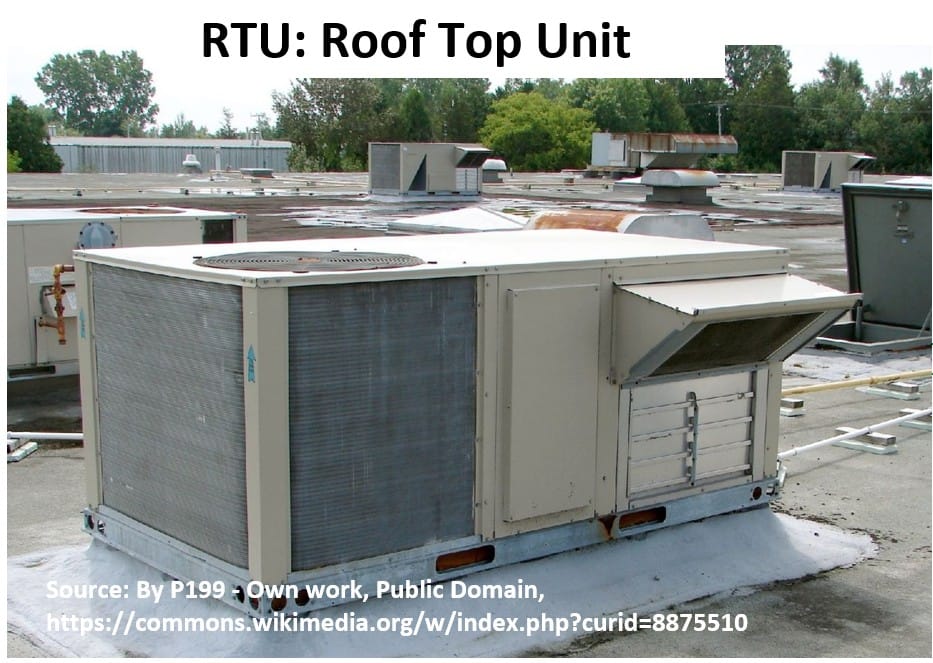
Schematic – How RTUS Work – Engineering Mindset Drawing
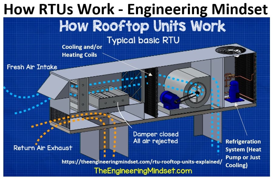
Note, the bulleted descriptions below apply to the Gas/Electric Pack (The “Gas Pack”) type of RTU (arguably the traditional setup).
But be aware there are other types utilizing different heating and cooling technologies (e.g. Heat Pump RTU, Dual-Fuel / Hybrid RTU, and Electric/Electric RTU
- Name: Packaged Gas/Electric (Gas Pack / RTU = Rooftop Unit)
- Ducted / Ductless / Hydronic: Ducted
- Heat Carrier / Heat Absorber in Heating and Cooling Mode:
- Cooling Mode: Refrigerant absorbs heat from return air and rejects it directly to the outdoor air through a self-contained condenser section.
- Heating Mode: No refrigerant heat absorption; gas burners heat the central air stream directly.
- Heating Technology: Gas combustion chamber featuring a single-stage, multi-stage, or modulating gas valve paired with an integrated burner assembly inside the packaged cabinet.
- Cooling Technology: Factory-sealed, self-contained vapor-compression refrigeration cycle.
- Configuration: All-in-one packaged footprint sitting entirely outdoors, typically mounted on a flat-roof curb or a ground-level concrete pad. It connects directly to the building interior via large supply and return duct drops.
- Typical Application: Commercial flat-roof buildings (retail stores, offices, restaurants) and single-story residential homes with strict indoor space limits.
- Main Factors Favoring this Application: Eliminates indoor equipment mechanical noise, preserves indoor square footage, and simplifies installation and servicing with single-point utility connections.
4. Dual-Fuel / Hybrid Systems
A smart mix of a gas furnace and an electric heat pump that swap jobs depending on how cold it is outside.
- Name: Dual-Fuel / Hybrid System
- Ducted / Ductless / Hydronic: Ducted
- Heat Carrier / Heat Absorber in Heating and Cooling Mode:
- Cooling Mode: Refrigerant absorbs heat from indoor air and rejects it to outdoor air.
- Heating Mode (Mild weather): Refrigerant absorbs heat from outdoor air and delivers it indoors.
- Heating Mode (Extreme cold): No refrigerant absorption; gas burner heats air directly.
- Heating Technology: Automatically toggles between an electric air-source heat pump (for high efficiency in mild weather) and a fossil fuel furnace (for maximum capacity in extreme cold).
- Cooling Technology: Standard or inverter-driven vapor-compression refrigeration cycle via the heat pump component.
- Configuration: Split system: Outdoor air-source heat pump unit paired with an indoor fossil-fuel furnace (gas or propane) and an evaporator coil, utilizing a single central duct network.
- Typical Application: Residential homes in climates with hot summers and extremely volatile, freezing winters (e.g., US Midwest or Northeast).
- Main Factors Favoring this Application: Optimizes utility bills by shifting between electricity and gas based on outdoor temperatures, ensures rapid heating during extreme freezes, and extends equipment lifespan.
Ductless & Single-Room Systems
These systems cool or heat specific spots and do not need large, built-in home ducts.
5 Ductless Mini-Split / Multi-Split Heat Pump
Small units mounted on the wall inside (most commonly), hooked to an outdoor unit.
Picture: Ductless Mini-Split or Multi-Split Heat Pump
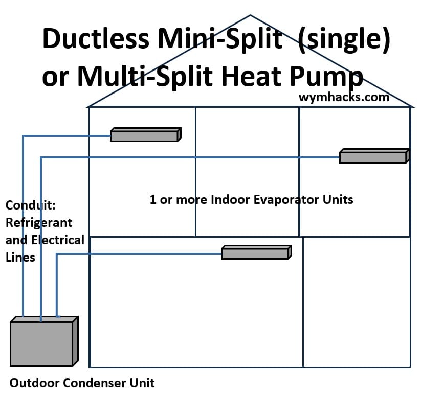
- Name: Ductless Mini-Split / Multi-Split Heat Pump
- Ducted / Ductless / Hydronic: Ductless
- Heat Carrier / Heat Absorber in Heating and Cooling Mode:
- Cooling Mode: Refrigerant absorbs heat directly from room air via localized indoor units and rejects it to the outdoor ambient air.
- Heating Mode: Refrigerant absorbs heat from the outdoor ambient air and carries it directly to specific indoor units to heat the room air.
- Heating Technology: Variable-speed, inverter-driven vapor-compression cycle. High-performance models often include flash-injection or vapor-injection compressors to maintain heating capacity in sub-zero outdoor temperatures.
- Cooling Technology: Inverter-driven variable-speed vapor-compression refrigeration cycle, modulating compressor speed to match the precise cooling load of the space.
- Configuration: One outdoor unit (containing a variable-speed compressor) connected via small, flexible refrigerant line sets and electrical wiring directly to one (Mini-Split) or up to eight (Multi-Split) independent, zone-specific indoor fan-coil units mounted directly on walls, ceilings, or floors.
- Typical Application: Home additions, historical building retrofits lacking space for mechanical ductwork, multi-family apartment conversions, and targeted correction of hot/cold spots in specific rooms.
- Main Factors Favoring this Application: Total absence of existing ductwork, strict physical architectural constraints, a desire for high energy efficiency via room-by-room zoning, and situations where operating costs can be lowered by only conditioning occupied spaces.
6. PTAC & PTHP (Hotel Wall Units)
- PTAC stands for Packaged Terminal Air Conditioner
- PTHP stands for Packaged Terminal Heat Pump
The boxes built under the window in hotel rooms.
Picture: PTAC
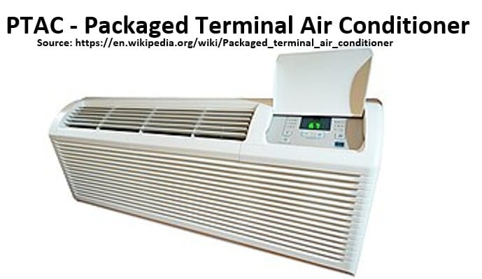
- Name: PTAC (Cooling only or Cooling + Electric Heat) and PTHP (Heat Pump version)
- Ducted / Ductless / Hydronic: Ductless
- Heat Carrier / Heat Absorber in Heating and Cooling Mode:
- Cooling Mode: Refrigerant absorbs heat from the single room’s air and rejects it directly through the exterior wall grille to the outside air.
- Heating Mode (PTHP): Refrigerant absorbs heat from the outdoor air and rejects it into the single room’s air.
- Heating Mode (Standard PTAC): No refrigerant heat absorption; it uses electric resistance coils or an internal hot water/steam coil to heat the room air directly.
- Heating Technology: For PTHPs, a standard vapor-compression cycle with a reversing valve, accompanied by auxiliary electric resistance heat for cold temperatures. For standard PTACs, pure electric resistance heating elements.
- Cooling Technology: Self-contained, fixed-speed vapor-compression refrigeration cycle.
- Configuration: A single, self-contained “packaged” unit housed entirely within a sleeve that passes through an exterior wall. All components—compressor, indoor/outdoor coils, fans, and controls—are in one box. It requires no refrigerant piping.
- Typical Application: Hotel and motel guest rooms, senior living facilities, hospital patient rooms, and small dormitories.
- Main Factors Favoring this Application: Low initial equipment cost, ease of installation, completely independent localized control for single rooms, and simplified maintenance (a broken unit can be slid out of the wall sleeve and replaced with a spare in minutes by standard maintenance staff without an HVAC license).
7. Window Units & Portable A/Cs
Small units you plug into a wall and stick in a window for summer.
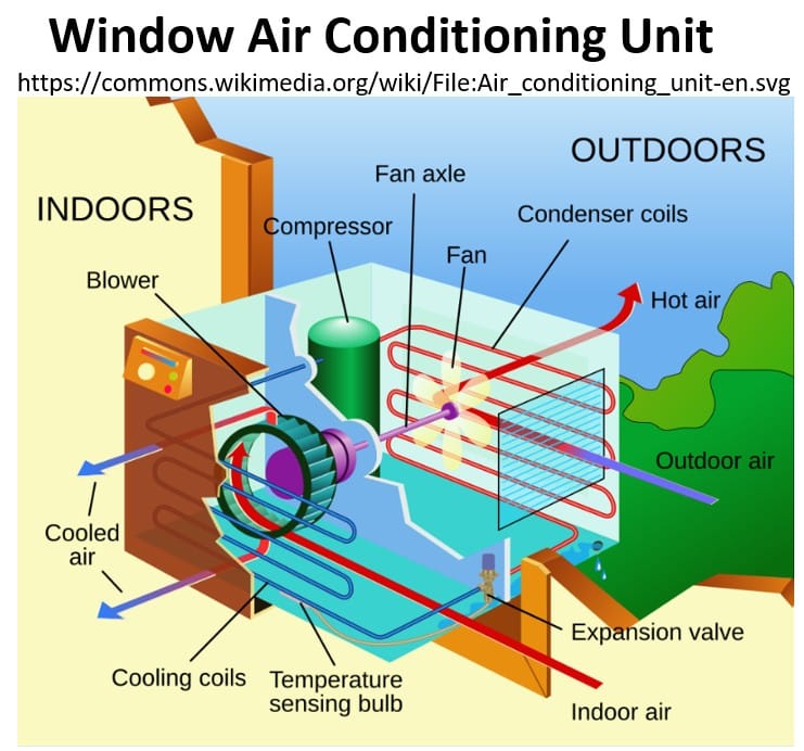
Refrigeration Process
- Indoor air sucked in and cooled across coils and blown back into room
- Hot Refrigerant compressed and condensed.
- Outside part of unit: Outdoor Air Sucked in (and blown out as hot air) the outside part to help with condensing
- Refrigerant is expanded (de-pressured and cooled) to repeat the cycle)
- Name: Window Air Conditioner / Portable Air Conditioner
- Ducted / Ductless / Hydronic: Ductless
- Heat Carrier / Heat Absorber in Heating and Cooling Mode:
- Cooling Mode: Refrigerant absorbs heat from the room air and rejects it directly to the outdoors.
- Heating Mode (Rare Heat Pump variants): Refrigerant absorbs heat from the outdoor air and rejects it indoors.
- Heating Mode (Common variants): Most units are cooling-only; rare models include built-in electric resistance coils.
- Heating Technology: Primarily none (cooling-only), but when heating is present, it is achieved via electric resistance heating elements or a basic, low-ambient-limited vapor-compression cycle.
- Cooling Technology: Compact, self-contained, fixed-speed (or occasionally entry-level inverter) vapor-compression refrigeration cycle.
- Configuration:
- Window Unit: A single enclosed box containing all components sitting directly in a window frame or a dedicated wall hole, separating the indoor side from the outdoor side via an internal insulated partition.
- Portable A/C: A mobile unit sitting entirely inside the room on casters. It pulls indoor air to cool the condenser coil and exhausts that hot air outside through one or two flexible plastic hoses connected to a window slider kit.
- Typical Application: Rental apartments, older residential homes lacking central HVAC, temporary or seasonal cooling, workshops, and backup cooling during central system failures.
- Main Factors Favoring this Application: Extremely low capital cost, zero permanent installation infrastructure required, high mobility/portability, and the ability for consumers to purchase, install, and operate the unit immediately without professional labor.
8. High-Velocity / Small-Duct High-Velocity (SDHV) Systems
Uses tiny, flexible tubes instead of big ducts.
Great for putting modern air into old, historic homes.
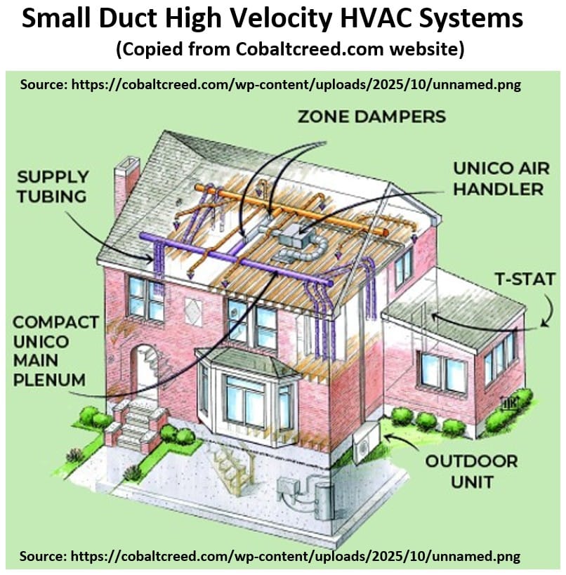
- Name: High-Velocity / Small-Duct High-Velocity (SDHV) System
- Ducted / Ductless / Hydronic: Ducted
- Heat Carrier / Heat Absorber in Heating and Cooling Mode:
- Cooling Mode: Refrigerant or chilled water absorbs heat from indoor air across a deeply insulated, high-latency cooling coil.
- Heating Mode: No outdoor absorption; relies on an attached gas furnace, heat pump coil, or hydronic heating loop.
- Heating Technology: Can tie into a specialized high-velocity heat pump loop, a hydronic heating coil loop fed by a boiler, or a traditional gas furnace.
- Cooling Technology: High-pressure vapor-compression refrigeration cycle utilizing a specialized indoor coil designed to operate at low airflows without frosting.
- Configuration: A high-pressure air handler connected to small, flexible, heavily insulated supply tubes (2-inch to 3-inch inner diameter) threaded through standard wall cavities and floor joists, terminating in small, unnoticeable round vents.
- Typical Application: Historic home restorations, architectural retrofits with zero space for standard rectangular bulkhead ducts, and high-end modern custom homes.
- Main Factors Favoring this Application: Minimal structural impact, can be threaded through standard framing without modifications, high moisture removal capacity, and draft-free aspiration mixing.
Water-Based Systems (Hydronic)
Instead of blowing air to move heat, these systems pump hot or cold water through pipes in the floors or walls.
9. Boiler System
A classic heater that warms water for radiators (and other uses like hot water for showers).
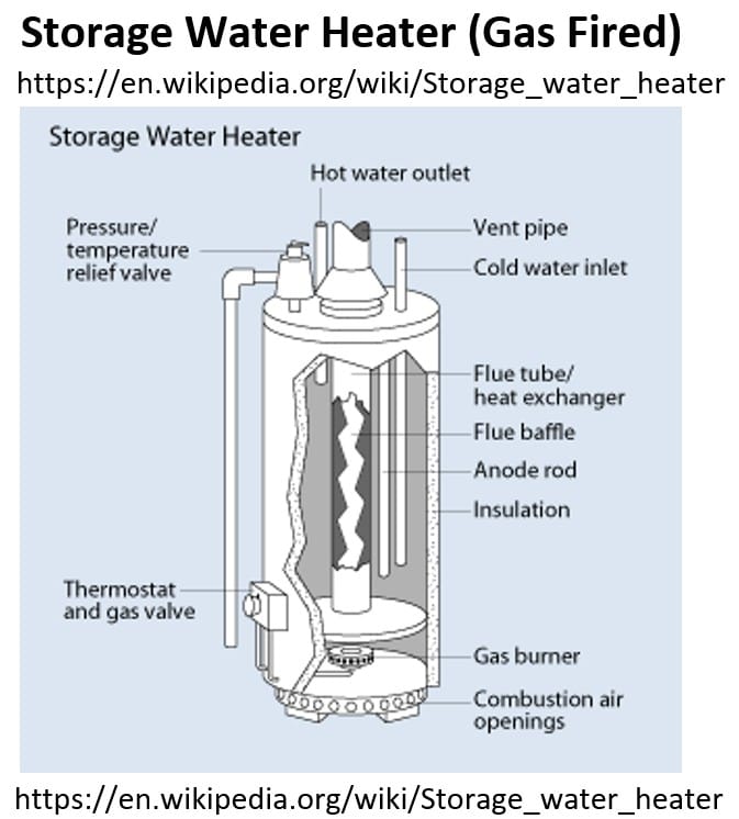
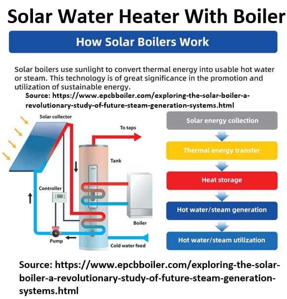
- Name: Boiler System
- Ducted / Ductless / Hydronic: Hydronic
- Heat Carrier / Heat Absorber in Heating and Cooling Mode:
- Cooling Mode: None (heating only).
- Heating Mode: Water or steam absorbs heat from combustion or electricity and carries it to the space via piping.
- Heating Technology: Combustion of fossil fuels (gas, oil, propane) or electric resistance elements heating water inside a cast iron, steel, or copper tube pressure vessel.
- Cooling Technology: None. Requires a separate, independent cooling system if air conditioning is needed.
- Configuration: Central boiler unit connected via a network of insulated piping to terminal units (radiators, baseboards, or fan coils) across the building.
- Typical Application: Older residential homes, multi-family apartment buildings, and schools in cold climates.
- Main Factors Favoring this Application: Exceptional heating comfort, long equipment lifespan, silent operation, and highly effective performance in extreme sub-zero temperatures.
I am familiar with one boiler system that I think is common in the middle east. The details of this setup are described below.
- Name: Hybrid Solar-Diesel Boiler System (Central Heating / Chofage)
- Ducted / Ductless / Hydronic: Hydronic
- Heat Carrier / Heat Absorber in Heating and Cooling Mode:
- Cooling Mode: None (heating only).
- Heating Mode: Water or a glycol-water mix absorbs heat from solar thermal collectors or fuel combustion, carrying it to the space via a closed piping network.
- Heating Technology: Dual-source hybrid thermal generation. Primary source: Rooftop solar thermal collectors (evacuated tubes or flat plates) that directly absorb solar radiation to heat the fluid. Secondary/Backup source: A diesel-fired (fuel oil) combustion boiler pressure vessel that automatically triggers via a thermostat when solar gain is insufficient to reach required heating temperatures.
10. Air-to-Water Heat Pump
How Air to Water Heat Pump Work – Powerworld Heat Pump
Uses outdoor air to heat or cool water for your floors or sinks.
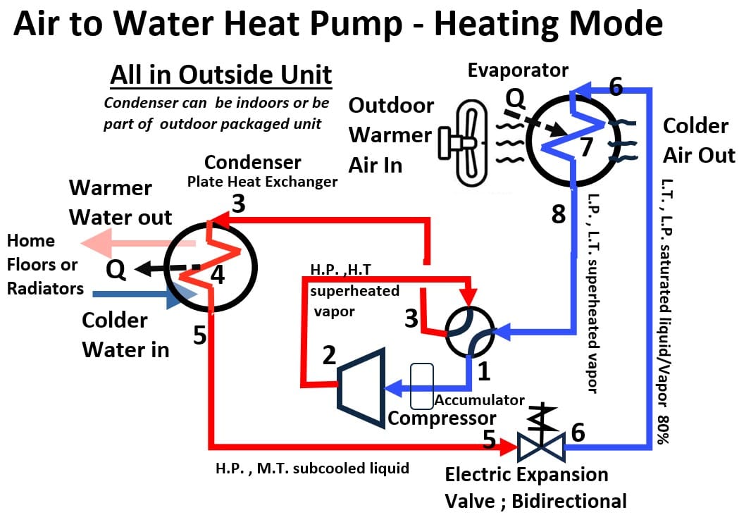
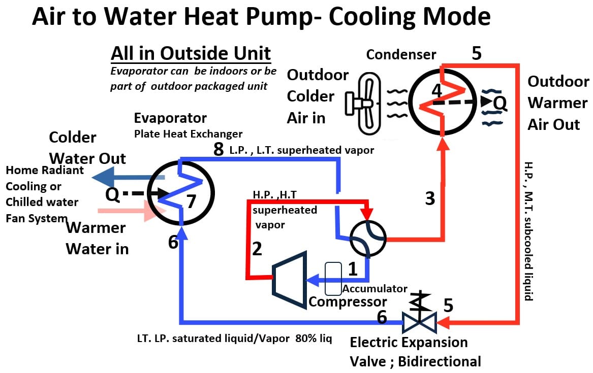
- Name: Air-to-Water Heat Pump
- Ducted / Ductless / Hydronic: Hydronic
- Heat Carrier / Heat Absorber in Heating and Cooling Mode:
- Cooling Mode: Warm water returning from the building releases its heat into the refrigerant loop inside the indoor heat exchanger, causing the water to cool down before returning to the indoor terminals. The hot refrigerant then travels to the outdoor heat exchanger, where it rejects that absorbed heat to the outdoor air.
- Heating Mode: Refrigerant absorbs heat from the outdoor air via the outdoor heat exchanger. After compression, this hot refrigerant travels to the indoor heat exchanger and releases its heat into the circulating water loop, causing the water to heat up before it is pumped to the building’s terminals.
- Heating Technology: Vapor-compression cycle utilizing an outdoor air-source heat exchanger (evaporator) to absorb ambient heat, and an indoor refrigerant-to-water heat exchanger (condenser) to transfer that heat into the hydronic loop.
- Cooling Technology: Vapor-compression cycle reversing its flow so the indoor refrigerant-to-water heat exchanger acts as the evaporator—absorbing heat from the circulating water loop to chill it—while the outdoor heat exchanger acts as the condenser to reject that heat to the outdoor air.
- Configuration: An outdoor packaged or split heat pump unit where the critical energy exchange happens at an indoor water-to-refrigerant heat exchanger, which connects directly to the building’s internal hydronic plumbing network.
- Typical Application: Modern low-energy homes, multi-family retrofits, and commercial buildings looking to transition away from fossil-fuel boilers while retaining or installing hydronic infrastructure.
- Main Factors Favoring this Application: Decarbonization goals (electrification of heating), high-efficiency zoning control, and the ability to utilize hydronic distribution (like radiant floors or chilled beams) without the high cost of drilling geothermal wells.
11. Radiant Floor Heating and Cooling Panels
Warm or cool pipes hidden right under your floorboards (or in the ceiling).
- Name: Radiant Floor Heating and Cooling Panels
- Ducted / Ductless / Hydronic: Hydronic
- Heat Carrier / Heat Absorber in Heating and Cooling Mode:
- Cooling Mode: Chilled water absorbs radiant heat from objects, people, and the structure of the space.
- Heating Mode: Hot water rejects heat, warming the floor surface which radiantly heats objects and occupants.
- Heating Technology: Hydronic loop embedded in concrete slabs or subfloor tracks, supplied by a boiler, heat pump, or solar thermal system.
- Cooling Technology: Hydronic loop supplying chilled water ( to ) calculated carefully to always remain safely above the indoor dew point.
- Configuration: Loops of flexible PEX tubing laid out in precise patterns embedded within the building’s floor structure, connected to localized mixing manifolds.
- Typical Application: Warehouses, aircraft hangars, open atriums, custom residential spaces, and high-ceiling lobbies.
- Main Factors Favoring this Application: Unmatched physical comfort, highly uniform temperature distribution, zero fan noise or air drafts, and exceptional efficiency due to lower required water temperatures.
12. Hydronic Fan Coil Units (FCUs)
Fan Coil Unit – Engineering Mindset
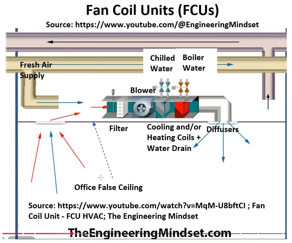
A water pipe with a small fan attached to blow air across it. (hot water for heating and cold water for chilling).
- Name: Hydronic Fan Coil Unit (FCU)
- Ducted / Ductless / Hydronic: Ductless or Short-Ducted
- Heat Carrier / Heat Absorber in Heating and Cooling Mode:
- Cooling Mode: Chilled water circulating through the coil absorbs heat directly from the room air.
- Heating Mode: Hot water circulating through the coil rejects heat into the room air.
- Heating Technology: Central boiler, heat pump, or steam plant providing hot water to the unit’s internal hydronic coil.
- Cooling Technology: Central chiller plant or air-to-water heat pump providing chilled water to the unit’s internal hydronic coil.
- Configuration: A localized terminal unit containing a water coil and a small fan. Can be 2-pipe (heating OR cooling seasonally) or 4-pipe (simultaneous heating AND cooling availability).
- Typical Application: Hotel rooms, dormitories, high-rise apartments, and individual office spaces.
- Main Factors Favoring this Application: Simple local zone control, low upfront cost for multi-room applications, and the space efficiency of running water pipes instead of major duct mains.
Earth & Water Source Systems (Geothermal)
These systems are ultra-efficient because they trap heat from the ground or a nearby water source instead of the outside air.
13. Geothermal (Ground Source) Heat Pump (Forced Air)
Uses underground loops to heat or cool air for ducts. (Water to Air Heat Pump).
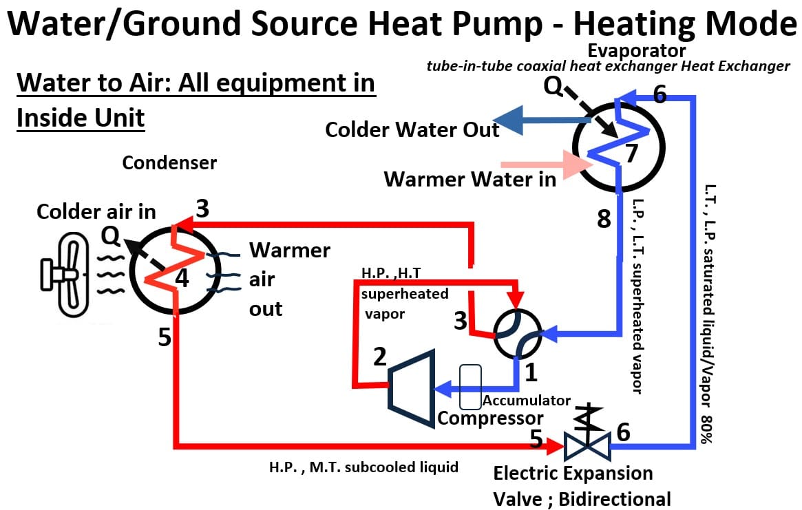
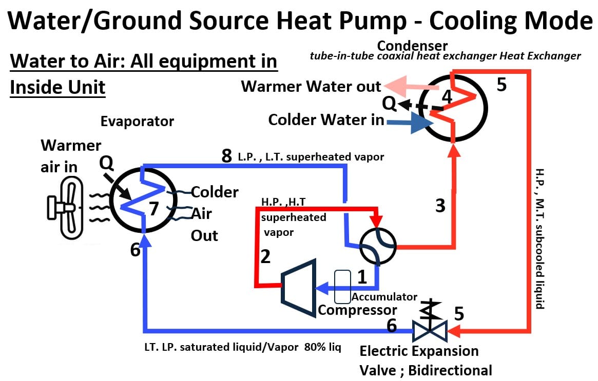
- Name: Geothermal Heat Pump (Forced Air)
- Ducted / Ductless / Hydronic: Ducted
- Heat Carrier / Heat Absorber in Heating and Cooling Mode:
- Cooling Mode: Refrigerant absorbs heat from indoor air and rejects it to the steady-temperature earth loop via a water-to-refrigerant heat exchanger.
- Heating Mode: Refrigerant absorbs heat from the earth loop and rejects it to the indoor air.
- Heating Technology: Vapor-compression cycle extracting heat from a closed or open ground loop ( to constant ground temp) and transferring it to an indoor air coil.
- Cooling Technology: Vapor-compression cycle reversing to reject indoor heat back down into the cool earth loop via the ground heat exchanger.
- Configuration: An indoor packaged unit containing the compressor, air blower, and water-to-refrigerant heat exchanger, connected to an underground loop of high-density polyethylene pipes and a central duct network.
- Typical Application: High-end eco-conscious residential homes, rural properties with ample land, and low-rise institutional buildings.
- Main Factors Favoring this Application: Extreme energy efficiency, lowest operating costs of any forced-air system, long equipment life, and a desire to eliminate visible outdoor units or fan noise.
14. Geothermal (Ground Source) Hydronic System
Uses underground loops to heat or cool water for floors (water to water heat pump)
See the two flow drawings in the previous section: Geothermal Heat Pump (Forced Air).
But now instead of indoor air being heated or cooled, we have a water system that is being heated or cooled.
- Name: Geothermal Hydronic System
- Ducted / Ductless / Hydronic: Hydronic (Feeds secondary loops)
- Heat Carrier / Heat Absorber in Heating and Cooling Mode:
- Cooling Mode: Water/antifreeze fluid absorbs building heat and rejects it into the steady-temperature earth loop via a liquid-to-liquid heat exchanger.
- Heating Mode: Water/antifreeze fluid absorbs thermal energy from the earth loop and delivers it to the building’s water loop.
- Heating Technology: Water-to-water vapor-compression cycle extracting heat from a closed or open ground loop ( to constant ground temp).
- Cooling Technology: Water-to-water vapor-compression cycle reversing to reject heat back down into the cool earth loop.
- Configuration: A central water-to-water heat pump connected to a vast network of underground high-density polyethylene pipes (vertical boreholes or horizontal trenches) and an indoor hydronic distribution loop.
- Typical Application: High-end eco-conscious residential homes, institutional campuses, and municipal buildings.
- Main Factors Favoring this Application: Lowest operating costs of any thermal system, massive long-term energy savings, zero visible outdoor equipment noise/footprint, and low environmental impact.
15. Water-Source Heat Pump: Water to Air
Often used in large buildings that share a big central water loop.
Has the same process flow as shown in section 13. Geothermal (Ground Source) Heat Pump (Forced Air)
- Name: Water-Source Heat Pump (Commercial)
- Ducted / Ductless / Hydronic: Ducted locally, tied to a central Hydronic loop.
- Heat Carrier / Heat Absorber in Heating and Cooling Mode:
- Cooling Mode: Local refrigerant absorbs heat from zone air and rejects it into a building-wide circulating water loop.
- Heating Mode: Local refrigerant absorbs heat from the shared building water loop and rejects it into the zone air.
- Heating Technology: Vapor-compression cycle using a localized refrigerant-to-water coaxial heat exchanger, supported by a central loop boiler.
- Cooling Technology: Vapor-compression cycle rejecting heat into the shared water loop, which is cooled by a central cooling tower or fluid cooler.
- Configuration: Multiple individual, self-contained packaged heat pump units located in closets/ceilings of each zone, all linked to a single continuous water loop piping network.
- Typical Application: Multi-tenant office buildings, high-rise condominiums, hotels, and multi-zone commercial spaces.
- Main Factors Favoring this Application: High energy recovery potential (units in cooling reject heat into the loop for heating units to use), simplified tenant sub-metering, and space-saving pipe routing compared to large ducts.
Large Commercial Systems & Specialized Systems
These are heavy-duty systems built for offices, skyscrapers, schools, or unique climates.
16. Variable Air Volume (VAV) Systems
Types of HVAC Systems – Young Architect Academy
VAV Variable Air Volume – Engineering Mindset
Picture: Variable Air Volume HVAC – Source (Engineering Mindset)
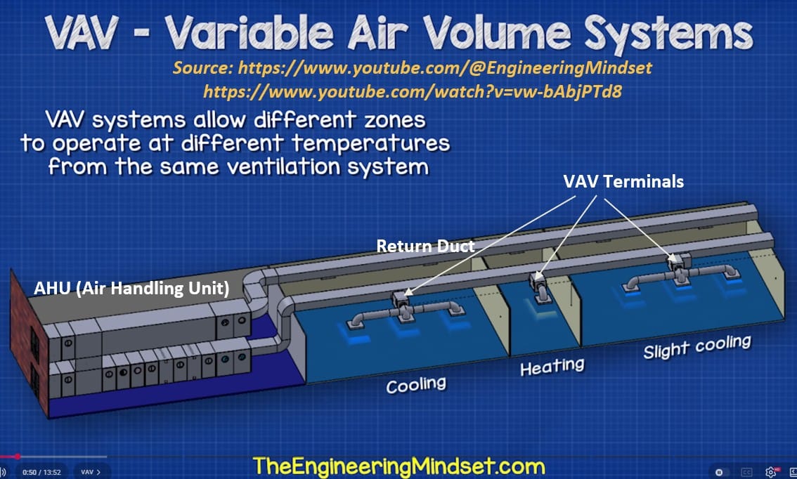
Modern office building systems that change how much air each room gets.
A Variable Air Volume (VAV) system is a commercial heating and cooling method that regulates indoor temperatures by varying the amount of conditioned air delivered to a space while keeping the air temperature constant.
A central air handling unit pushes cold air through a main duct network, which then splits into localized “VAV boxes” dedicated to individual rooms or zones.
As a room’s thermostat senses temperature changes, it signals a motorized damper inside the VAV box to open or close, adjusting the volume of air entering that specific space to maintain comfort efficiently.
- Name: Variable Air Volume (VAV) System
- Ducted / Ductless / Hydronic: Ducted
- Heat Carrier / Heat Absorber in Heating and Cooling Mode:
- Cooling Mode: Chilled water or central direct-expansion (DX) refrigerant loops absorb heat from a centralized air loop.
- Heating Mode: Central hot water or electric coils heat the primary air, often supplemented by localized reheat coils at individual terminal zones.
- Heating Technology: Central boiler/heating plant paired with local electric or hydronic reheat coils located inside individual zone-level VAV terminals.
- Cooling Technology: Centralized chilled water plants (chillers) or large modular multi-circuit direct-expansion (DX) compressor systems.
- Configuration: A large central AHU supplies constant-temperature cooled air (typically ) to the building. Variable speed drives vary the total airflow volume based on demand, while localized VAV boxes throttle internal dampers to adjust airflow for individual rooms.
- Typical Application: Medium-to-large multi-story commercial office buildings, corporate campuses, hospitals, and schools.
- Main Factors Favoring this Application: Superb energy efficiency via drastically reduced fan energy consumption, highly precise independent multi-zone temperature control, and lower long-term operating costs.
17. Constant Air Volume (CAV / CV) Systems
Types of HVAC Systems – Young Architect Academy
Older office systems that blow the same amount of air all day.
A Constant Air Volume (CAV) system keeps a building comfortable by blasting a steady, unchanging amount of air through the rooms at all times.
Instead of changing how much air is blowing, it adjusts the temperature of the air stream to make a space warmer or cooler.
Because the heavy fans always run at full speed, CAV systems use a lot of electricity, making them best for large, single open spaces like warehouses or gyms
- Name: Constant Air Volume (CAV / CV) System
- Ducted / Ductless / Hydronic: Ducted
- Heat Carrier / Heat Absorber in Heating and Cooling Mode:
- Cooling Mode: Refrigerant or chilled water absorbs heat from a centralized primary air stream.
- Heating Mode: Combusted gas, electric coils, or hot water loops reject heat directly into the centralized primary air stream.
- Heating Technology: Central heating plant (boiler, gas furnace, or steam plant) supplying thermal energy to a centralized air handler.
- Cooling Technology: Central direct-expansion (DX) refrigerant loop or a centralized chilled water plant loop.
- Configuration: A central air handling unit (AHU) that supplies a fixed, unchanging volume of air (measured in constant ) through a main duct trunk. Thermal control is adjusted by constantly cycling the heating/cooling sources on and off or modulating the air temperature.
- Typical Application: Large, single-zone open spaces like gymnasiums, auditoriums, warehouses, and small retail spaces with uniform thermal loads.
- Main Factors Favoring this Application: Low initial controls cost, straightforward mechanical design, and ideal for applications requiring high, constant ventilation/air circulation rates regardless of temperature swings.
18. VRF / VRV Systems (Variable Refrigerant Flow / Volume)
Advanced commercial setups that move refrigerant around a giant building to heat one room while cooling another.
While a standard heat pump uses an on-or-off approach to heat or cool an entire space as a single zone, a VRF/VRV system uses a variable-speed compressor to precisely deliver differing amounts of refrigerant to multiple indoor units, allowing for independent temperature control—and even simultaneous heating and cooling—in separate rooms.
VRF and VRV are actually the exact same technology. Daikin trademarked “VRV” when they invented it, so every other manufacturer calls it “VRF”
The Big Picture: How a Heat Recovery VRF System Works
In a heat recovery VRF system, the indoor units directly trade heat with each other through a central controller—using the waste heat from a cooling room to warm up a heating room.
Because the indoor rooms are balancing each other out, the outdoor coil never has to play two roles at once.
- It simply acts as a net-balancer:
- acting as a condenser to dump leftover heat if the building is mostly cooling,
- or as an evaporator to grab extra heat if the building is mostly heating.
How the Indoor Units Enact Reverse Flow
To pull this off, a central Branch Controller box manages a 3-pipe main line from the outdoor unit and splits it into two pipes for each individual indoor unit.
Inside each indoor unit, the refrigerant flows through a dedicated Electronic Expansion Valve (EEV) and the heat exchanger coil.
By manipulating the Branch Controller and the EEV, the system literally reverses the direction of flow through those two pipes depending on what the room asks for:
In Cooling Mode (Forward Flow): Liquid refrigerant enters the unit through the first pipe, passes through the expansion valve (where it drops in pressure and gets freezing cold), flows into the heat exchanger to absorb room heat, and exits through the second pipe as a gas. The unit acts as an evaporator.
In Heating Mode (Reverse Flow): The system flips the script. Scorching-hot gas enters from the opposite direction through the second pipe, flows into the heat exchanger first to dump heat into the room, and passes through the expansion valve afterward as it exits through the first pipe. The unit acts as a condenser.
By constantly reversing the inlet and outlet roles of those two pipes, every indoor unit can instantly switch between acting as its own independent heater or air conditioner on a single, shared system.
Schematic – 3 Pipe VRF Design With Independent Indoor Heating and Cooling
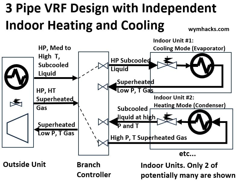
How the Outdoor Unit Works
In a VRF heat recovery system, the outdoor unit constantly changes its operation to match the building’s main needs.
When the building has a net cooling demand,
- the outdoor unit uses its heat exchanger as a condenser to dump trapped indoor heat into the sky,
- creating more high-pressure liquid refrigerant to cool the rooms.
- refrigerant to compressor to condenser to liquid refrigerant supply to inside units
Conversely, when the building has a net heating demand,
- the outdoor unit switches roles and uses its heat exchanger as an evaporator to steal ambient heat from the outside air,
- which the compressor squeezes to produce hot, high-pressure gas for indoor warmth
- refrigerant to evaporator to compressor to hot gas supply to inside units
Schematic – 3 Pipe VRF Design: Outdoor System Refrigerant Flow
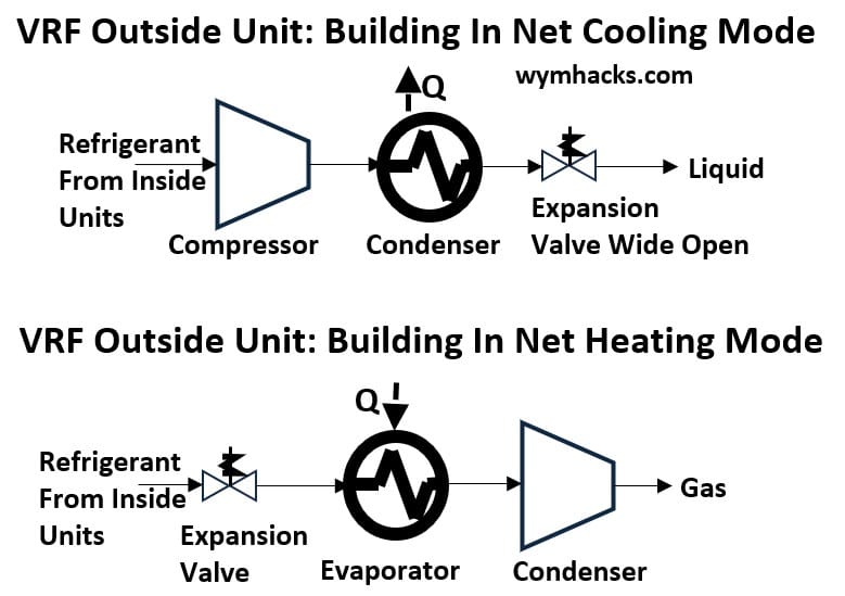
- Name: Variable Refrigerant Flow (VRF) or Variable Refrigerant Volume (VRV) System
- Ducted / Ductless / Hydronic: Ducted, Ductless, or a Hybrid mix.
- Heat Carrier / Heat Absorber in Heating and Cooling Mode:
- Cooling Mode: Refrigerant absorbs heat from multiple independent indoor zones and rejects it to the outdoor air (or to a water loop).
- Heating Mode: Refrigerant absorbs heat from the outdoor air (or water loop) and distributes it to the indoor zones.
- Heat Recovery Mode: Refrigerant absorbs heat from zones requiring cooling and directly transfers that heat to zones requiring heating, bypassing the outdoor unit entirely.
- Heating Technology: Multi-compressor, variable-speed inverter vapor-compression. In 3-pipe (or specialized 2-pipe) Heat Recovery configurations, it utilizes branch selector boxes to route gaseous or liquid refrigerant dynamically based on individual zone demands.
- Cooling Technology: Highly precise, variable-volume vapor-compression refrigeration that adjusts refrigerant mass flow to each individual indoor unit.
- Configuration: A single large outdoor condensing unit (or a localized bank of modular outdoor units) connected via a complex master network of branching copper refrigerant piping to dozens of independent indoor units across different floors, wings, or rooms.
- Typical Application: Medium-to-large commercial office buildings, hotels, schools, multi-family high-rises, and hospitals.
- Main Factors Favoring this Application: Buildings experiencing highly diverse, simultaneous heating and cooling loads (e.g., sunny southern offices vs. shaded northern offices), strict corporate energy efficiency goals, limited vertical plenum space for massive air ducts, and a demand for premium, decentralized localized temperature control.
19. Chilled Beams (Active & Passive)
Chilled beams are ceiling-mounted heating and cooling units that use water instead of air to condition a room.
How do Chilled Beams Work – MEP Academy
NSW HVAC Academy – What are Chilled Beams?
- Name: Chilled Beams (Active & Passive)
- Ducted / Ductless / Hydronic: Hydronic / Air Hybrid
- Heat Carrier / Heat Absorber in Heating and Cooling Mode:
- Cooling Mode: Chilled water inside the beam coil absorbs room heat via natural convection (Passive) or induced airflow (Active).
- Heating Mode: Hot water inside the beam coil radiates heat downward to warm the space.
- Heating Technology: Hydronic heating loop supplying hot water to the beam coil (primarily Active beams; Passive beams rarely heat due to air buoyancy physics).
- Cooling Technology: Hydronic cooling loop supplying chilled water adjusted above the room’s dew point temperature to prevent condensation.
- Configuration:
- Passive: Ceiling-mounted induction coils relying entirely on natural air buoyancy.
- Active: Ceiling-mounted induction coils integrated with a small primary air supply duct from a central DOAS unit.
- Typical Application: Laboratories, commercial office spaces, schools, and hospitals with high sensible cooling loads.
- Main Factors Favoring this Application: Near-silent operation, exceptional energy efficiency, draft-free thermal comfort, and drastically reduced ceiling plenum space requirements.
20. Dedicated Outdoor Air Systems (DOAS)
Systems just for bringing fresh outside air into large buildings.
Dedicated Outdoor Air Systems (DOAS) – MEP Academy
Picture: DOAS Source (MEP Academy)
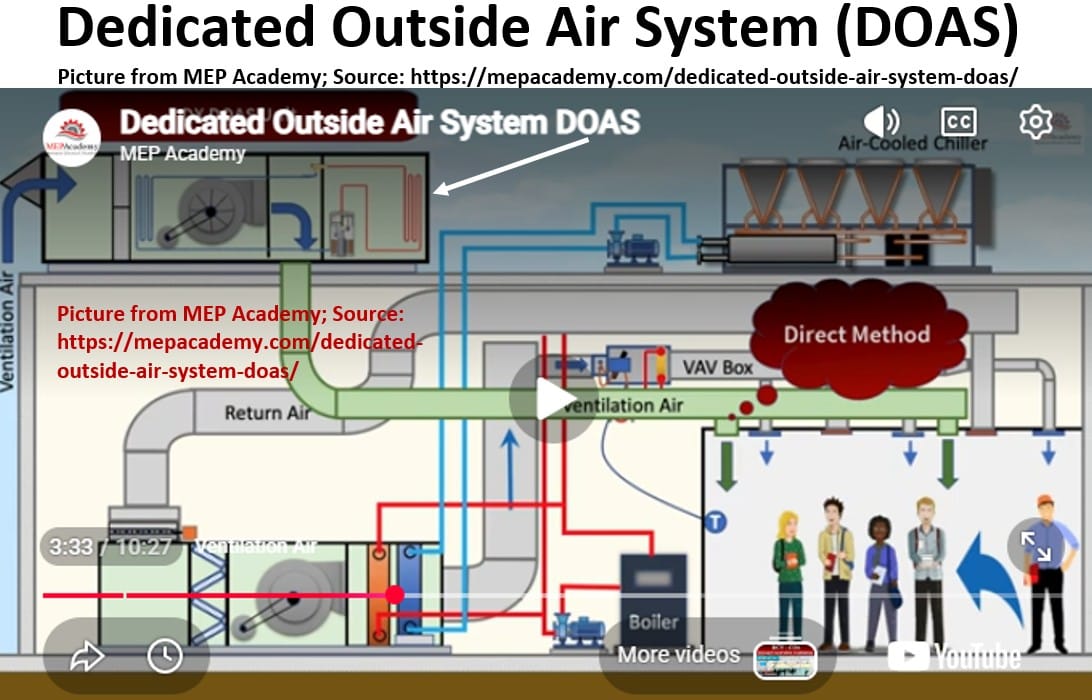
A DOAS is designed to handle the heavy ventilation needs of spaces packed with people, like office buildings, schools, hotels, medical facilities, assisted living facilities etc.
The DOAS mainly does four things:
- 1. 100% Fresh Air Delivery (Ventilation)
- 2. Extreme Humidity Control (Dehumidification)
- 3. Heavy-Duty Filtration
- 4. Thermal “Neutralization” (Pre-Heating/Pre-Cooling)
- Name: Dedicated Outdoor Air System (DOAS)
- Ducted / Ductless / Hydronic: Ducted
- Heat Carrier / Heat Absorber in Heating and Cooling Mode:
- Cooling Mode: Chilled water or a dedicated refrigerant direct-expansion (DX) circuit absorbs heat and moisture from raw outdoor air to dry it out.
- Heating Mode: Hot water, gas burners, or DX circuits reject heat to temper cold incoming outdoor air.
- Heating Technology: Gas burner, electric resistance, or hot-gas reheat (recovering waste heat from the cooling cycle to warm dehumidified air).
- Cooling Technology: Vapor-compression DX cycle or chilled water coil, highly optimized for heavy latent cooling (moisture removal) loads.
- Configuration: A specialized air handler dedicated solely to treating 100% outside air. It filters, cools/heats, and dehumidifies fresh outdoor ventilation air before delivering it directly to spaces or to secondary local HVAC units.
- Typical Application: Modern high-efficiency commercial buildings, schools, hotels, and laboratories paired with terminal units (like VRF or chilled beams).
- Main Factors Favoring this Application: Decouples the ventilation load from the space heating/cooling load, guarantees precise outdoor air delivery rates for indoor air quality, and prevents indoor humidity issues.
21. District Energy Connections (District Heating / Cooling)
When a whole city block hooks up to one giant, shared heating or cooling plant.
Picture – District Heating/Cooling Systems. Source (International District Energy Association)
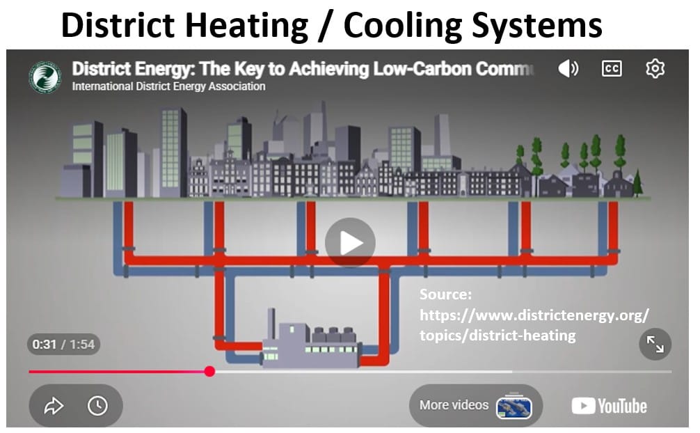
- Name: District Energy Connection (District Heating / Cooling)
- Ducted / Ductless / Hydronic: Hydronic (Feeds building-level systems)
- Heat Carrier / Heat Absorber in Heating and Cooling Mode:
- Cooling Mode: Chilled water from a municipal plant absorbs building heat via a central heat exchanger.
- Heating Mode: Steam or hot water from a municipal plant rejects heat into the building loop.
- Heating Technology: No on-site combustion or boilers; utilizes hot water or high-pressure steam piped from a central municipal or campus utility plant through a Heat Exchanger (HEX).
- Cooling Technology: No on-site chillers or compressors; utilizes chilled water piped from a centralized municipal plant through a building-level Heat Exchanger.
- Configuration: A building-level mechanical room containing Energy Transfer Stations (ETS) consisting of massive plate-and-frame heat exchangers, pumps, and energy meters, with zero on-site thermal generation equipment.
- Typical Application: Downtown commercial high-rises, university campuses, hospital complexes, and high-density urban residential districts.
- Main Factors Favoring this Application: Eliminates the need for on-site boilers, chillers, and cooling towers; dramatically reduces building peak electrical demands; reclaims premium roof/basement square footage; and lowers localized maintenance.
22. Thermal Energy Storage (Ice Storage Systems)
Thermal Energy Storage – MEP Academy
Pictures – Thermal Energy Storage (ICE) Cooling System
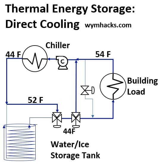
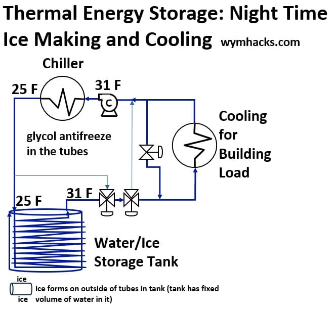
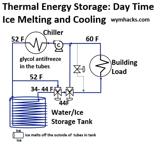
Making ice at night when power is cheap, then using it to cool a building during the day.
- Name: Thermal Energy Storage (Ice Storage System)
- Ducted / Ductless / Hydronic: Hydronic / Central Plant Hybrid
- Heat Carrier / Heat Absorber in Heating and Cooling Mode:
- Cooling Mode: Chilled water or glycol solution absorbs building heat and rejects it into ice tanks (melting ice) during peak hours, or directly to chillers.
- Heating Mode: None (cooling-capacity optimization only).
- Heating Technology: None. This is a load-shifting technology strictly integrated into a central cooling plant.
- Cooling Technology: Uses standard central chillers operating at night to freeze water in storage tanks, then melts the ice during the day to provide cooling capacity without running the chillers at peak times.
- Configuration: A central chiller plant paired with large, heavily insulated fluid tanks containing water or modular ice coils, integrated into the building’s primary chilled water loop.
- Typical Application: Large commercial office buildings, corporate headquarters, sports arenas, and manufacturing facilities with high daytime peak cooling loads.
- Main Factors Favoring this Application: Slashes peak electrical demand charges by shifting heavy chiller operation to cheaper off-peak nighttime utility rates; allows for smaller, downsized chiller equipment configurations.
23. Evaporative Coolers (Swamp Coolers)
A special alternative to A/C that only works in hot, bone-dry desert climates (e.g. South-West United States).
Picture: Evaporative Pad (Swamp Cooler) – Source(Wikipedia)
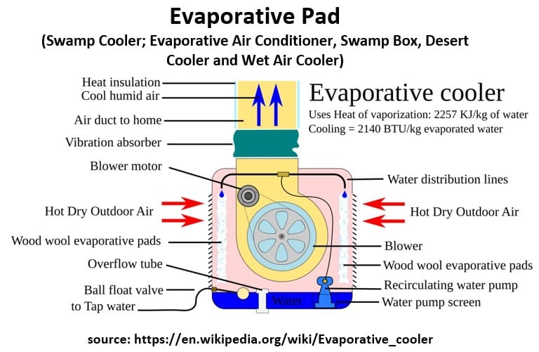
- Name: Evaporative Cooler (Swamp Cooler)
- Ducted / Ductless / Hydronic: Ducted or Ductless
- Heat Carrier / Heat Absorber in Heating and Cooling Mode:
- Cooling Mode: Outdoor air passes through water-saturated pads; water evaporates (latent heat of vaporization), absorbing sensible heat from the air and lowering its dry-bulb temperature.
- Heating Mode: None. Requires a completely separate heating system.
- Heating Technology: None. Purely a cooling and ventilation technology.
- Cooling Technology: Evaporative cooling (latent heat of vaporization). No chemical refrigerants or compressors are used.
- Configuration: A packaged outdoor unit mounted on a roof or side wall containing a water pump, wet cooling pads, and a large blower fan that pushes 100% fresh, humidified air into the space.
- Typical Application: Residential homes, warehouses, workshops, and agricultural buildings in arid, low-humidity climates.
- Main Factors Favoring this Application: Exceptionally low equipment and electricity costs, simple mechanical maintenance, and climates with very low ambient relative humidity (e.g., US Southwest).
Return to HVAC Overview Section.
Appendix 5 – Twenty Three HVAC Types – Tabulated
- Return to HVAC Overview Section.
- Return to HVAC type heating cooling mode table
Standard Home Systems
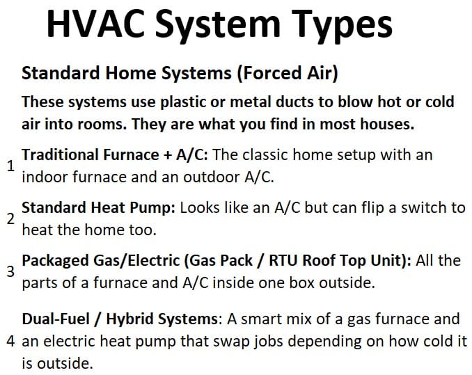
Ductless & Single-Room Systems
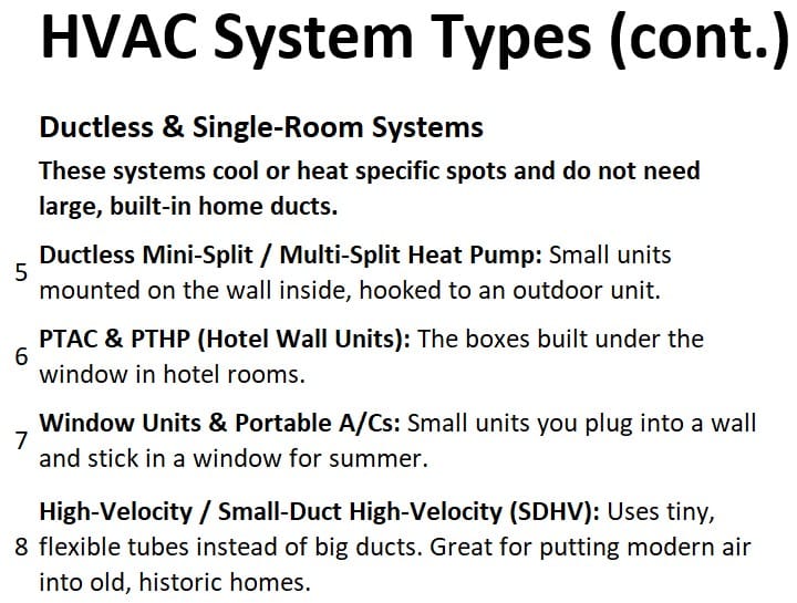
Water-Based Hydronic Systems
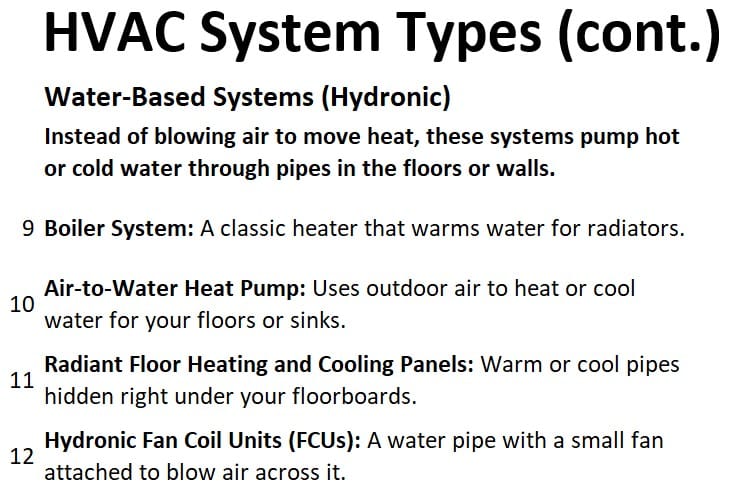
Ground & Water Source Systems (Geothermal)
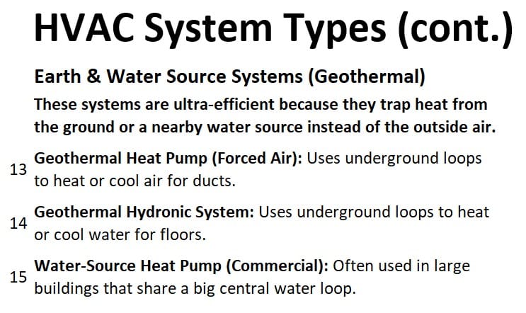
Large Commercial Systems and Specialized Systems
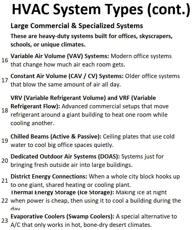
Return to HVAC Overview Section.
Appendix 6 – Heat Pump Types
- Return to HVAC Overview Section.
- Return to HVAC type heating cooling mode table
Table – Heat Pumps Types Global Market Share
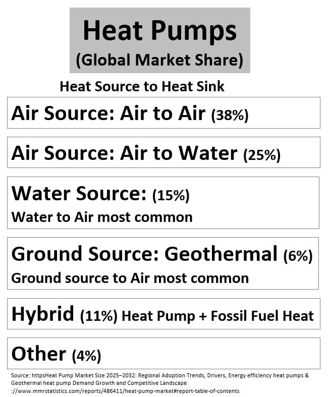
Air Source Heat Pump: Air (Heat Source) to Air (Heat Sink)
Lets start with the cycle for an Air-to-Air Heat Pump.
In heating mode , the indoor coil acts as the condenser to heat the house, and the outdoor coil acts as the evaporator to absorb ambient heat.
Schematic – Air to Air Heat Pump (AAHP) – Heating Mode
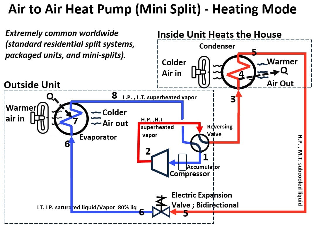
AAHP_Heating_Mode_Compressor Discharge → Indoor Coil (Acting as the Condenser)
- The Journey: The refrigerant leaves the compressor (located outside) and flows indoors to the indoor coil.
- Role: The indoor coil is acting as the Condenser.
- Energy Exchange: The indoor fan blows cool room air across this hot coil. The refrigerant rejects heat to the indoor air. The source of the heat is the energy absorbed from outdoors plus the compressor work; the heat is going into your living space.
- Thermodynamic State: Entering the coil: High-pressure, high-temperature superheated vapor.
- Inside the coil: As it rejects heat, it transitions through a saturated vapor/liquid mixture.
- Leaving the coil: It exits as a high-pressure, mid-temperature subcooled liquid.
AAHP_Heating_Mode_Indoor Coil → Expansion Valve
- The Journey: The high-pressure, mid-temperature subcooled liquid leaves the indoor coil (condenser) and travels back outside to the expansion valve (located in the outdoor unit).
- The Process: The valve creates a restriction, causing a rapid drop in pressure and temperature.
- Thermodynamic State: The refrigerant undergoes flash evaporation, leaving the valve as a low-pressure, low-temperature saturated liquid/vapor mixture (mostly liquid).
AAHP_Heating_Mode_Expansion Valve → Outdoor Coil (Acting as the Evaporator)
- The Journey: This cold mixture enters the outdoor coil.
- Role: The outdoor coil is acting as the Evaporator.
- Energy Exchange: Because the refrigerant is colder than the outdoor air, it absorbs heat from the outdoor ambient air. The source is the outdoor air; the heat is going into the refrigerant.
- Thermodynamic State: Inside the coil: It boils through a saturated liquid/vapor mixture, turning completely into a vapor.
Leaving the coil: It picks up a few extra degrees of heat at the very end of the coil, exiting as a low-pressure, low-temperature superheated vapor.
AAHP_Heating_Mode_Outdoor Coil → Compressor Suction
The Journey: The low-pressure, low-temperature superheated vapor leaves the outdoor coil (evaporator) and enters the compressor suction port, where it is compressed back into a superheated gas to restart the cycle.
In cooling mode, the coils reverse their function. The indoor coil acts as the evaporator to cool the house, and the outdoor coil acts as the condenser to reject heat outside.
Schematic – Air to Air Heat Pump – Cooling Mode
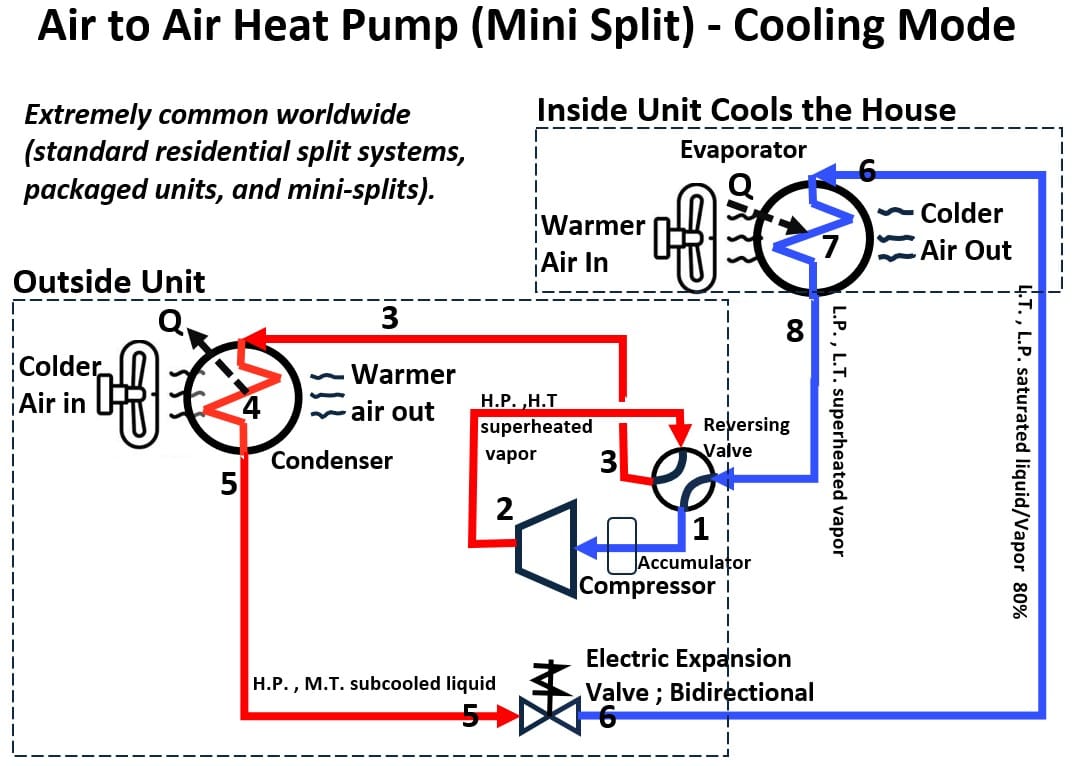
AAHP_Cooling_Mode_Compressor Discharge → Outdoor Coil (Acting as the Condenser)
- The Journey: The refrigerant leaves the compressor (outside) and is routed to the outdoor coil.
- Role: The outdoor coil is acting as the Condenser.
- Energy Exchange: The outdoor fan blows ambient air across the hot coil. The refrigerant rejects heat to the outdoor air. The source of the heat is your house; the heat is going into the outdoor environment.
- Thermodynamic State: * Entering the coil: High-pressure, high-temperature superheated vapor.
- Inside the coil: It condenses through a saturated vapor/liquid mixture.
- Leaving the coil: It exits as a high-pressure, mid-temperature subcooled liquid.
AAHP_Cooling_Mode_Outdoor Coil→ Expansion Valve
- The Journey: The high-pressure, mid-temperature subcooled liquid leaves the outdoor coil (condenser) and moves through the expansion valve (usually located indoors, right before the indoor coil).
- The Process: The valve drops the pressure sharply, lowering its temperature.
- Thermodynamic State: It leaves the valve as a low-pressure, low-temperature saturated liquid/vapor mixture.
AAHP_Cooling_Mode_Expansion Valve→ Indoor Coil (Acting as the Evaporator)
- The Journey: The cold mixture enters the indoor coil.
- Role: The indoor coil is acting as the Evaporator.
- Energy Exchange: Warm indoor air is blown across the coil. The refrigerant absorbs heat from your indoor air. The source of heat is your indoor air; the heat is going into the refrigerant to cool your home.
- Thermodynamic State: * Inside the coil: It evaporates through a saturated liquid/vapor mixture.
Leaving the coil: It exits the indoor coil as a low-pressure, low-temperature superheated vapor.
AAHP_Cooling_Mode_Indoor Coil→ Compressor Suction
The Journey: The low-pressure, low-temperature superheated vapor travels back outside from the indoor coil (evaporator) and goes directly into the compressor suction to be compressed again.
Air to Air Heat Pump_Market Prevalence & Configuration
- How Common: Extremely common worldwide (standard residential split systems, packaged units, and mini-splits).
- Application: Almost always provided for both heating and cooling via a reversing valve.
Air Source Heat Pump: Air (Heat Source) to Water (Heat Sink)
Instead of blowing air over a coil to heat or cool a house, a Air-to-Water Air Source Heat Pump (AWHP) uses an outdoor unit to exchange heat with the air, and an indoor heat exchanger to transfer that energy into a hydronic water loop (which feeds radiant floor heating, radiators, or fan coil units).
In heating mode, the outdoor air coil acts as the evaporator to absorb ambient heat, and the indoor refrigerant-to-water heat exchanger acts as the condenser to heat the water loop.
Schematic – Air to Water Heat Pump (AWHP) – Heating Mode
AWHP_Heating Mode _Compressor Discharge → Indoor Heat Exchanger (Acting as the Condenser)
- The Journey: The refrigerant leaves the compressor (located in the outdoor unit) and flows to the indoor heat exchanger (often a plate heat exchanger sitting inside the home or inside a packaged outdoor hydro-box).
- Role: This heat exchanger is acting as the Condenser. Inside this component, refrigerant loops right next to a closed water loop without mixing.
- Energy Exchange: The hot refrigerant rejects heat into the circulating water loop. The source of the heat is the outdoor ambient air plus compressor work; the heat is going into the water, which is then pumped to your floors or radiators.
- Thermodynamic State: * Entering: High-pressure, high-temperature superheated vapor.
- Inside: It condenses through a saturated vapor/liquid mixture.
- Leaving: It exits as a high-pressure, mid-temperature subcooled liquid.
AWHP_Heating Mode _Indoor Heat Exchanger → Expansion Valve
- The Journey: The high-pressure, mid-temperature subcooled liquid leaves the indoor heat exchanger (condenser) and travels to the expansion valve (located in the outdoor unit).
- The Process: The valve creates a restriction, dropping the pressure and temperature rapidly.
- Thermodynamic State: The refrigerant undergoes flash evaporation, leaving the valve as a low-pressure, low-temperature saturated liquid/vapor mixture.
AWHP_Heating Mode _Expansion Valve → Outdoor Coil (Acting as the Evaporator)
- The Journey: This cold mixture enters the outdoor coil (sitting outside).
- Role: The outdoor coil is acting as the Evaporator.
- Energy Exchange: An outdoor fan blows ambient air across the coil. Because the refrigerant is colder than the outside air, it absorbs heat from the outdoor air. The source is the outdoor air; the heat goes into the refrigerant.
- Thermodynamic State:
- Inside: It boils through a saturated liquid/vapor mixture.
- Leaving: It picks up a tiny bit of extra heat at the exit, leaving the coil as a low-pressure, low-temperature superheated vapor.
AWHP_Heating Mode _Outdoor Coil → Compressor Suction
The Journey: The low-pressure, low-temperature superheated vapor leaves the outdoor coil (evaporator) and enters the compressor suction port to be compressed again.
In cooling mode, the roles reverse. The indoor heat exchanger acts as the evaporator to chill the water loop, and the outdoor coil acts as the condenser to dump the house’s heat outside.
Schematic – Air to Water Heat Pump – Cooling Mode
AWHP_Cooling_Mode_Compressor Discharge → Outdoor Coil (Acting as the Condenser)
- The Journey: The refrigerant leaves the compressor (outside) and goes directly into the outdoor coil (sitting outside).
- Role: The outdoor coil is acting as the Condenser.
- Energy Exchange: The outdoor fan blows ambient air across the hot coil, and the refrigerant rejects heat to the outdoor air. The source of the heat is your house’s water loop; the heat is going into the outdoor environment.
- Thermodynamic State:
- Entering: High-pressure, high-temperature superheated vapor.
- Inside: It condenses through a saturated vapor/liquid mixture.
- Leaving: It exits as a high-pressure, mid-temperature subcooled liquid.
AWHP_Cooling_Mode_Outdoor Coil → Expansion Valve
- The Journey: The high-pressure, mid-temperature subcooled liquid leaves the outdoor coil (condenser) and passes through the expansion valve (located outdoors).
- The Process: The valve drops the pressure sharply, making the refrigerant freezing cold.
- Thermodynamic State: It leaves the valve as a low-pressure, low-temperature saturated liquid/vapor mixture.
AWHP_Cooling_Mode_Expansion Valve → Indoor Heat Exchanger (Acting as the Evaporator)
- The Journey: The cold mixture enters the indoor heat exchanger (sitting inside).
- Role: The indoor heat exchanger is acting as the Evaporator.
- Energy Exchange: The water loop circulates through the heat exchanger. The refrigerant absorbs heat from the water, chilling the water loop (which can then be used for radiant cooling or chilled-water fan coils). The source of heat is the indoor water loop; the heat goes into the refrigerant.
Thermodynamic State:
- Inside: It evaporates through a saturated liquid/vapor mixture.
- Leaving: It exits the heat exchanger as a low-pressure, low-temperature superheated vapor.
AWHP_Cooling_Mode_Indoor Heat Exchanger → Compressor Suction
The Journey: The low-pressure, low-temperature superheated vapor travels from the indoor heat exchanger (evaporator) back into the compressor suction to restart the cycle.
Air to Water Heat Pumps – Market Prevalence & Configuration
- How Common: Globally, its popularity varies wildly. In Europe and parts of Asia, it is highly common and growing rapidly due to the prevalence of existing hydronic radiator and radiant floor systems. In North America, it is historically uncommon/niche, though gaining traction for custom high-efficiency builds.
- Application: While they can be provided as heating-only (very common in cold European climates where air conditioning isn’t traditionally installed), most modern units are reversible and capable of both heating and cooling. Note: Cooling with an air-to-water system requires careful control of water temperatures to prevent condensation on floors/radiators, or the use of specialized fan coils with drain pans.
Water Source and Ground Source Heat Pumps: Water/Ground (Heat Source) to Air (Heat Sink)
Ground Source (geothermal) and Water Source heat pumps use the exact same internal refrigeration cycle.
The only difference is where the water loop goes once it leaves the machine.
- In a Water Source system, the loop connects to a shared building-wide water loop (common in high-rise condos or office buildings).
- In a Ground Source system, the loop goes deep into the earth or a pond.
Water-to-Air (WAHP) is the most common configuration for these systems.
Instead of an outdoor unit, the entire machine sits inside (usually in a mechanical closet, basement, or ceiling plenum).
In heating mode,
- the unit extracts heat from the water loop and rejects it into the indoor air.
- The indoor air coil acts as the condenser, and the coaxial water-to-refrigerant heat exchanger acts as the evaporator.
Schematic – Water Source or Ground Source Heat Pump – Heating Mode
WAHP_Heating_Mode_Compressor Discharge → Indoor Air Coil (Acting as the Condenser)
- The Journey: The refrigerant leaves the compressor (located inside the unit, indoors) and flows to the indoor air coil (also sitting inside the unit).
- Role: The indoor air coil is acting as the Condenser.
- Energy Exchange: The indoor blower fan pushes cold return air across this hot coil. The refrigerant rejects heat into the indoor air. The source of the heat is the water loop (ground/building loop) plus the compressor work; the heat is going directly into your home’s ductwork.
- Thermodynamic State: * Entering: High-pressure, high-temperature superheated vapor.
- Inside: It condenses through a saturated vapor/liquid mixture.
- Leaving: It exits the air coil as a high-pressure, mid-temperature subcooled liquid.
WAHP_Heating_Mode_Indoor Air Coil → Expansion Valve
- The Journey: The high-pressure, mid-temperature subcooled liquid leaves the air coil (condenser) and flows to the expansion valve (located inside the unit).
- The Process: The valve creates a restriction, dropping the pressure and temperature instantly.
- Thermodynamic State: The refrigerant undergoes flash evaporation, leaving the valve as a low-pressure, low-temperature saturated liquid/vapor mixture.
WAHP_Heating_Mode_Expansion Valve → Water Heat Exchanger (Acting as the Evaporator)
- The Journey: This cold mixture enters the water-to-refrigerant heat exchanger (often a tube-in-tube coaxial heat exchanger, sitting inside the indoor unit).
- Role: The water heat exchanger is acting as the Evaporator. Water from the ground or building loop circulates through this component right next to the refrigerant.
- Energy Exchange: Because the refrigerant is colder than the entering loop water, it absorbs heat from the water. The source of heat is the water/ground loop; the heat goes into the refrigerant. (Note: This leaves the water exiting the unit a few degrees colder than when it entered).
- Thermodynamic State:
- Inside: It boils through a saturated liquid/vapor mixture.
- Leaving: It picks up a bit of superheat at the end, exiting as a low-pressure, low-temperature superheated vapor.
WAHP_Heating_Mode_Water Heat Exchanger → Compressor Suction
The Journey: The low-pressure, low-temperature superheated vapor leaves the water heat exchanger (evaporator) and passes through the reversing valve straight into the compressor suction port to restart the cycle.
In cooling mode, the roles reverse.
The indoor air coil becomes the evaporator to cool the house, and the water heat exchanger becomes the condenser to reject heat into the water loop.
Schematic – Water Source or Ground Source Heat Pump – Cooling Mode
WAHP_Cooling_Mode_Compressor Discharge → Water Heat Exchanger (Acting as the Condenser)
- The Journey: The refrigerant leaves the compressor (indoors) and is routed to the water-to-refrigerant heat exchanger (indoors).
- Role: The water heat exchanger is acting as the Condenser.
- Energy Exchange: Cool water from the ground or building loop flows through the exchanger. The hot refrigerant rejects heat into this water loop. The source of the heat is your indoor air; the heat is going into the water loop to be dumped into the ground or a cooling tower.
- Thermodynamic State:
- Entering: High-pressure, high-temperature superheated vapor.
- Inside: It condenses through a saturated vapor/liquid mixture.
- Leaving: It exits as a high-pressure, mid-temperature subcooled liquid.
WAHP_Cooling_Mode_Water Heat Exchanger → Expansion Valve
- The Journey: The high-pressure, mid-temperature subcooled liquid leaves the water heat exchanger (condenser) and moves to the indoor expansion valve.
- The Process: The valve drops the pressure sharply, making the refrigerant freezing cold.
- Thermodynamic State: It leaves the valve as a low-pressure, low-temperature saturated liquid/vapor mixture.
WAHP_Cooling_Mode_Expansion Valve → Indoor Air Coil (Acting as the Evaporator)
- The Journey: The cold mixture enters the indoor air coil (indoors).
- Role: The indoor air coil is acting as the Evaporator.
- Energy Exchange: Warm indoor air is blown across the coil. The refrigerant absorbs heat from the air, cooling and dehumidifying your home. The source of heat is your indoor air; the heat goes into the refrigerant.
- Thermodynamic State:
- Inside: It evaporates through a saturated liquid/vapor mixture.
- Leaving: It exits the air coil as a low-pressure, low-temperature superheated vapor.
WAHP_Cooling_Mode_Indoor Air Coil → Compressor Suction
The Journey: The low-pressure, low-temperature superheated vapor travels from the air coil (evaporator) back into the compressor suction to be compressed again.
Water to Air Heat Pumps Market Prevalence & Configuration
- How Common: Highly common in specific sectors. It is the dominant choice for commercial high-rises, hotels, and large school systems utilizing a boiler/cooling tower loop. For residential applications, it is the standard choice for geothermal (ground source) installations.
- Application: Almost universally provided for both heating and cooling. Because ground temperatures and building loop temperatures stay relatively mild year-round, these units operate at incredibly high efficiencies in both modes.
Hybrid Heat Pump Systems
A hybrid heat pump system—often called a dual-fuel system—intelligently pairs an electric air-source heat pump with a conventional gas or oil furnace, sharing the same indoor ductwork to optimize both comfort and energy costs.
The entire system is orchestrated by a smart thermostat that acts as the brain, continuously monitoring the outdoor temperature and utility rates to decide which heating source is most efficient at any given moment.
- During mild spring and autumn days, the electric heat pump operates as the primary heat source, extracting ambient heat from the outside air with incredible efficiency.
- However, as winter deepens and outdoor temperatures plummet toward a specific “economic balance point,” the heat pump’s efficiency drops, and the system seamlessly shuts it down to engage the fossil-fuel furnace.
- This transition ensures the home receives the rapid, high-temperature heat output that furnaces excel at producing during extreme cold, while completely bypassing the need for expensive electric backup heat strips.
- Furthermore, because the heat pump is fully reversible, it acts as a standard central air conditioner during the summer months, making the hybrid configuration a highly versatile, year-round climate solution.
Market Prevalence & Configuration
How Common: Highly common and rapidly growing, particularly in regions that experience extreme seasonal temperature swings (such as the US Midwest, Northeast, and parts of Canada) or areas with volatile utility prices.
It is a favorite retrofitting strategy because homeowners can keep their existing functional furnace and simply swap their old AC unit for a heat pump.
Application: Universally provided for both heating and cooling. It delivers cooling and mild-weather heating via the heat pump, and extreme-weather heating via the furnace.
Return to HVAC Overview Section.
Appendix 7 – HVAC Applications in Different US IECC Zones
- Return to HVAC Overview Section.
- Return to HVAC type heating cooling mode table
The IECC ( International Energy Conservation Code) (along with ASHRAE – American Society of Heating, Refrigerating and Air-Conditioning Engineers. ) establishes the official climate zones used across the United States to dictate HVAC sizing, insulation requirements (R-values), and window efficiency standards.
The system breaks the US down into
- 8 primary climate zones based on temperature (numbered 1 to 8, moving from hottest to coldest),
- which are further divided by three moisture regimes (designated by letters A, B, and C).
The Numbered Temperature Zones
- Zone 1: Very Hot (e.g., Hawaii, Florida Keys)
- Zone 2: Hot (e.g., Southern Texas, parts of Florida)
- Zone 3: Warm (e.g., American South, Southern California)
- Zone 4: Mixed (e.g., Mid-Atlantic, Pacific Northwest)
- Zone 5: Cool (e.g., Midwest, Northeast)
- Zone 6: Cold (e.g., Northern Plains, Northern New England)
- Zone 7: Very Cold (e.g., Northern Minnesota, parts of Alaska)
- Zone 8: Subarctic (e.g., Interior Alaska)
The Moisture Regimes
- A (Moist): Regions with high rainfall, mostly east of the Rockies.
- B (Dry): Arid and semi-arid regions, mostly in the Southwest.
- C (Marine): Mild, damp coastal regions, primarily the Pacific Northwest coast.
When HVAC technicians calculate your heating and cooling loads (using Manual J calculations), or when builders install insulation, they look up your specific county on the IECC map (e.g., “Zone 4A” or “Zone 3B”) to figure out exactly how much capacity your equipment needs.
Map: IECC US Climate Zones
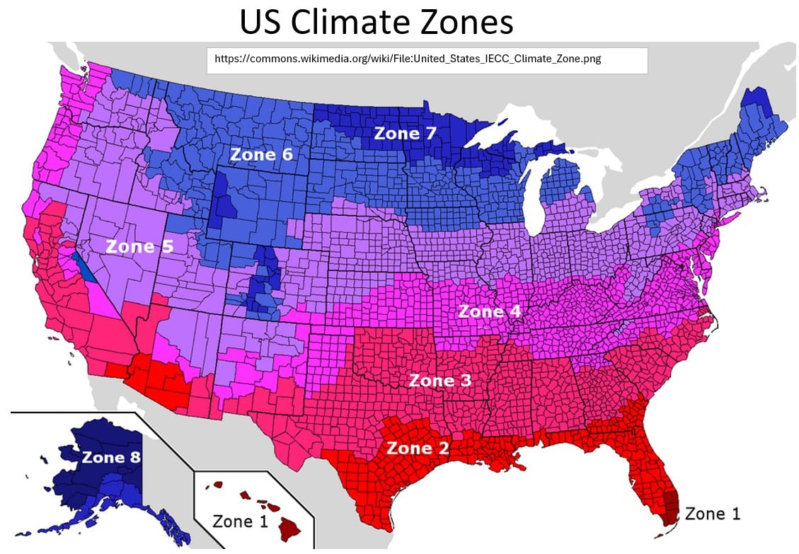
Typical HVAC Applications by Climate Zone
IECC Zone 1
Environment: Hyper-Hot & Humid
- Extreme sensible/latent summer loads
- Zero real winter (<50 heating hours/year)
Typical HVAC: Central Ducted Straight-Cool AC
- Outside condenser + indoor ducted air handler.
Backup / Auxiliary Heating Source: Electric Resistance Heat Strips
- Low upfront installation cost; rarely energized.
IECC Zone 2
Environment: Hot & Humid (Gulf Coast)
- Prolonged, heavy summer cooling load
- Brief winters with rare, short-lived freezes
Typical HVAC: Central Ducted Straight-Cool AC + Gas Furnace
- Standard AC paired with an 80% AFUE gas furnace. Uses cheap, abundant local gas lines. (Electric heat strips used in all-electric neighborhoods).
Backup / Auxiliary Heating Source: Natural Gas Combustion or Electric Heat Strips
IECC Zone 3
Environment: (East) Mixed-Humid / Transitional
- Moderate summers
- Consistently chilly winters; regular frost but no deep ground freezes
Typical HVAC: Central Ducted Heat Pump
- Single outdoor unit with reversing valve operating through standard central ductwork.
Backup / Auxiliary Heating Source: Electric Resistance Heat Strips
• Automatically kicks in during occasional hard freezes.
IECC Zone 3
Environment: (Central/West) Hot & Arid / Hot-Dry
- High sensible cooling loads; low humidity
- Chilly desert nights; icy winters in central regions
Typical HVAC: Central Ducted Straight-Cool AC + Gas Furnace
- Straight AC condenser paired with a standard gas furnace due to highly established local gas utility infrastructure.
Backup / Auxiliary Heating Source: Natural Gas Combustion
IECC Zone 4
Environment: Mixed-Humid & Marine
- Balanced heating and cooling demands
- Regular winter freezing; warm to hot summers
Typical HVAC: Dual-Fuel Hybrid System (East) / Ducted or Ductless Heat Pump (Marine)
- East utilizes a heat pump paired with a gas furnace. Marine utilizes heat pumps to replace old legacy furnace-only setups.
Backup / Auxiliary Heating Source: Gas Furnace (East) or Electric Heat Strips / Variable Inverter (Marine)
IECC Zone 5
Environment: Cold (The Furnace Territory)
- Severe, prolonged winters with deep freezes
- Short, intense summer cooling spikes
Typical HVAC: Central Ducted Straight-Cool AC + High-Efficiency Gas Furnace
- Focus is heavily on a 90%+ AFUE gas furnace to deliver high-temperature (120∘F+) supply air.
Backup / Auxiliary Heating Source: Natural Gas Combustion
- (Cold-climate inverter heat pumps rapidly gaining market share)
IECC Zone 6
Environment: Very Cold
- Extreme heating loads spanning 6 to 8 months
- Mild summers with low cooling demands
Typical HVAC: Gas/Propane Furnace + Standard AC (Central Ducted) or Hydronic Boiler + Ductless Mini-Split AC (Northeast)
- Older housing stock without ducts uses gas/oil boilers for baseboard heat and ductless mini-splits for summer cooling.
Backup / Auxiliary Heating Source: Natural Gas, Propane, or Fuel Oil Combustion
IECC Zones 7 & 8
Environment: Subarctic & Arctic
- Catastrophic winter temperatures (down to −40∘F)
- Cooling is entirely unnecessary
Typical HVAC: High-Output Fuel Oil / Propane Boilers or Furnaces
- Systems engineered exclusively for maximum winter BTU output. Air conditioning components are omitted.
Backup / Auxiliary Heating Source: Biomass (Wood/Pellets) or Propane
- Heavy focus on mechanical heating reliability for life safety.
Return to HVAC Overview Section.
Appendix 8 – HVAC Market Data (2025)
Return to HVAC Market Data Observations section.
Table: Global HVAC Market Share and Volume Index by Region
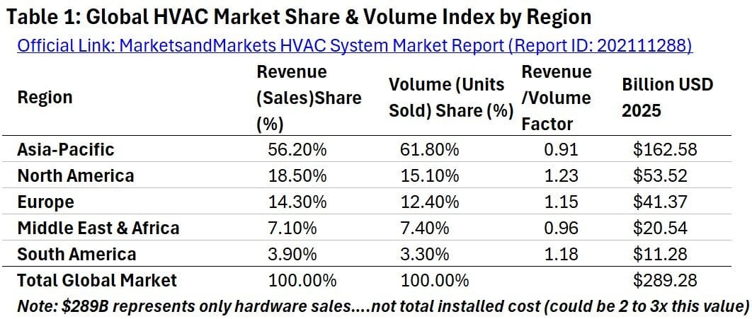
Table: Global HVAC Heat Pump Market by Type
Chart: Global HVAC Percent Market Share and Volume 2025
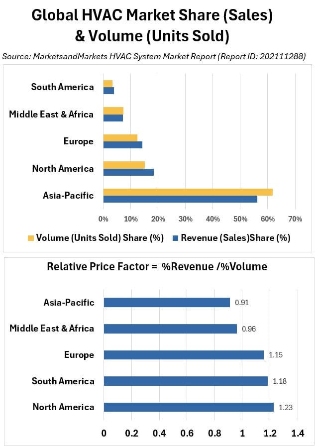
Chart: Global HVAC Market Share (Sales of Hardware Units) 2025
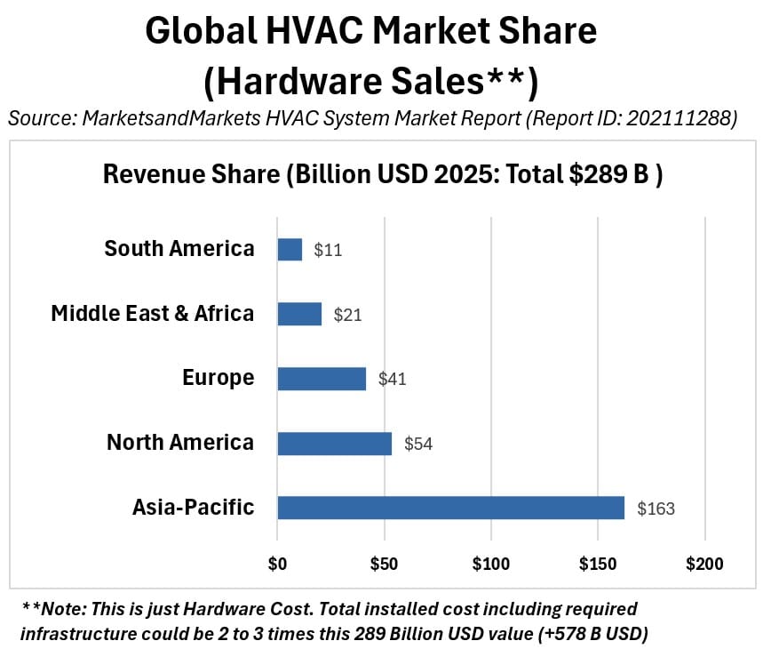
Table: Global HVAC Category Breakdown by Revenue (Sales) Market Share
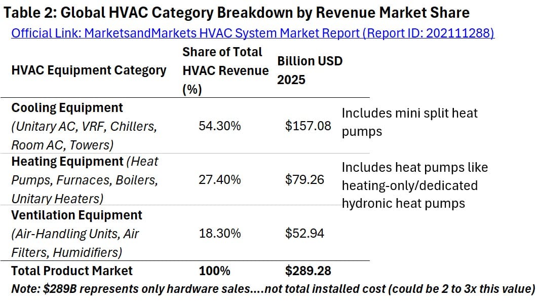
Table: Global HVAC Heat Pump Market by Type
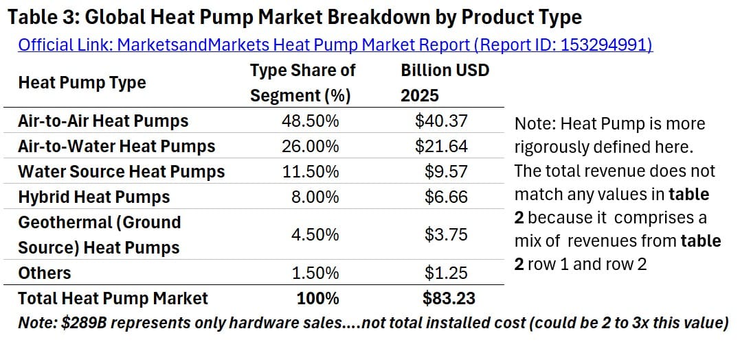
Chart: Global HVAC Heat Pump Market by Type
Table: Global HVAC Market; Commercial vs Residential
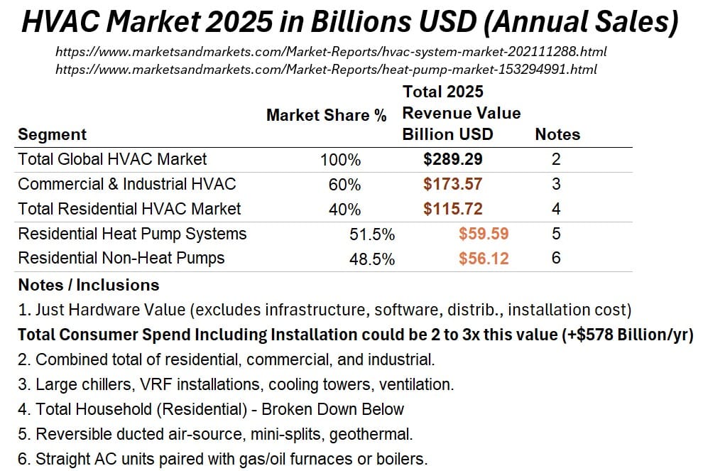
Chart: Global HVAC Market Commercial vs Residential
Return to HVAC Market Data Observations section.