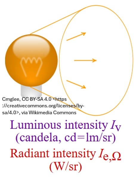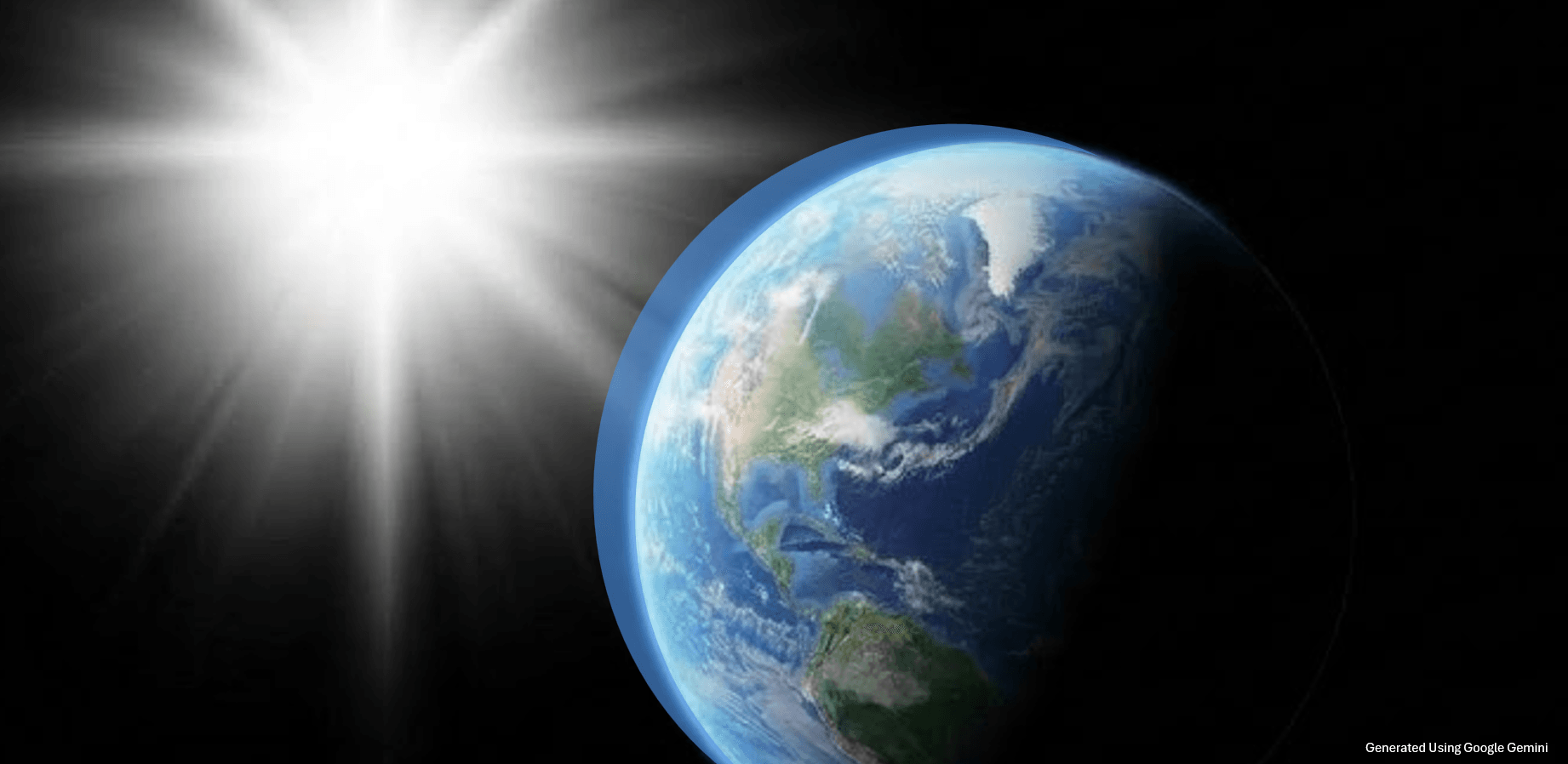
Introduction
Have you ever thought about why the sky is blue most of the day and why sunrises and sunsets usually involve orange/red colors?
The answer is that nitrogen and oxygen molecules (mostly) in the Earth’s atmosphere preferentially scatter certain components of sunlight.
These components of sunlight are often described by energy or wavelength or frequency.
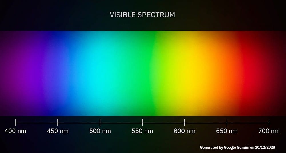
Lower wavelength light (on the purple/blue side in the picture below) simply scatters more than the longer wavelength light (the right orange/red part)
Picture: Visible Spectrum
Scattering Simply Explained
If you looked directly at the sun (don’t do that), during noon lets say, you would see white.
- White is simply the mix of all the visible colors shown above (remember that mnemonic ROYGBIV?)
- But if you look at the open sky away from the sun, what do you see? You will see some shade of blue.
- The blue component of light scatters more than the others colors so you see that color.
Well why don’t we see purple light scattered in the sky? Because it is true that it has a shorter wavelength than blue. There are two reasons for this.
- The intensity of the light in the purple range is weaker than the blue light
- Our retinal photo cells more naturally see blue vs purple
Why do we see Orange/Reg at Sunrise and Sunset
From your position, sunlight from the sun at the horizon (at sunrise or sunset) has to travel the furthest distance through the atmosphere to get to your eyes
- The distance through the atmosphere the light must go through is (roughly) 38 times more than when the sun is roughly straight above you.
- You can often look directly at the sun as it begins its ascent/descent.
- The shorter wavelengths have been completely scattered out as you look straight at the sun.
- So you see the high wavelength portion of the visible spectrum (the right side of the picture above i.e., orange and red).
- If you look away from the sun or above the sun, you will of course still see blue.

In this post, we’ll dig deeper to uncover some of the physics at play.
- I’ll start at the source, exploring the raw energy of the Sun and how we compute the solar constant.
- From there, I’ll trace how Earth’s atmosphere acts as a multi-layered filter, reducing solar radiation through ozone reactions, absorption, reflection, and scattering.
While every mechanism plays its part, the primary focus of this post is Rayleigh scattering ; the fundamental phenomenon responsible for the sky’s shifting colors.
We’ll break down the basic variables in its computation, examine the solar spectrum at both the top of the atmosphere and sea level to see where attenuation strikes hardest, and finally, we’ll derive the scattering cross-section equation.
Using it alongside a few key physical relationships, we will build a practical percentage scattering chart from the ground up.
Energy From The Sun
In order for us to understand climate on Earth, we have to understand how much energy it’s receiving from the Sun.
Inverse Square Law
Light energy must dilute in proportion to the expanding spherical area it travels.
The astronomer Johannes Kepler first articulated this in 1604.
Picture: Sunlight Irradiance and the Inverse Square Law
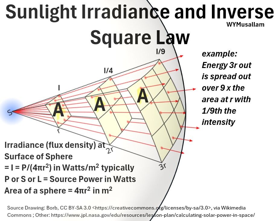
The total solar power (S for Solar power; or P for Power; or L for Luminosity) is the total radiant power (SI units = Watt = J/s) coming out of the Sun in all directions.
We can compute the amount of solar electromagnetic power (or radiant flux) received by a surface per unit area (the irradiance) as follows:
- I = Irradiance or flux density is the solar power received by a surface per unit area.
- Using the inverse square law, you take the Sun’s total output power (P), and spread it out over the surface area of an expanding imaginary sphere of radius r , (4π r²), centered on the Sun.
- When that energy hits Earth, you are calculating how much power is arriving per unit area.
- Units of measure: Power per unit area (Watts / m² = W / m² ).
i.e. , solar irradiance on a particular body in space is inversely proportional to the surface area of a sphere whose center is the Sun and whose radius is equal to the distance from that body to the Sun.
(ES1) I = S / (4πr2) ; Irradiance = Radiant Flux Density, or Intensity.
where
- I = solar irradiance = flux density (in Watts / m² = W / m² )
- S = total solar power (S for Solar power; or P for Power; or L for Luminosity) = the total radiant power (SI units = Watt = J/s) coming out of the Sun in all directions.
- r = distance from Sun to object.
- For Earth r = 149.6 million kilometers (about 93 million miles) = 1 Astronomical Unit = 1 au
Today we use a tool called an Electrical Substitution Radiometer to measure solar irradiance at the top of the Earth’s atmosphere (about 400 to 800 km or 250 to 500 miles above surface of Earth).
For Earth, Isun-earth = 1361 Watts/m2
(ES2) Isun-earth = 1361 Watts/m2 ; Solar Constant = Solar Irradiance (flux density) at the Top of the Earth’s Atmosphere
The Solar Constant is the average amount of solar electromagnetic radiation received per unit area at the top of Earth’s atmosphere, measured on a surface perpendicular to the Sun’s rays at a distance of one astronomical unit (distance from Sun to Earth).
So what is the value of S, the total solar power?
- The distance of the Earth from the Sun (astronomical unit) is 149.6 million kilometers (about 93 million miles).
- So we can calculate the total power of the Sun from the Inverse Square Law
- S = Isun-earth4πr2
- S = (1361 W/m2)(4π)(1.496×1011 meters)2
S = 3.8275..x 1026 Watts = 383 trillion trillion Watts = 383 Septillion Watts
For our discussions I is the important number, but just be aware that S is just mind – bogglingly large.
Average Power/m2 of Sun on Earth
Ok, we need to now average this solar constant (Isun-earth = 1361 Watts/m2 ) to the surface area of the Earth.
Check out my picture below as you read this section.
Picture: Average Solar Radiation is Solar Constant/4
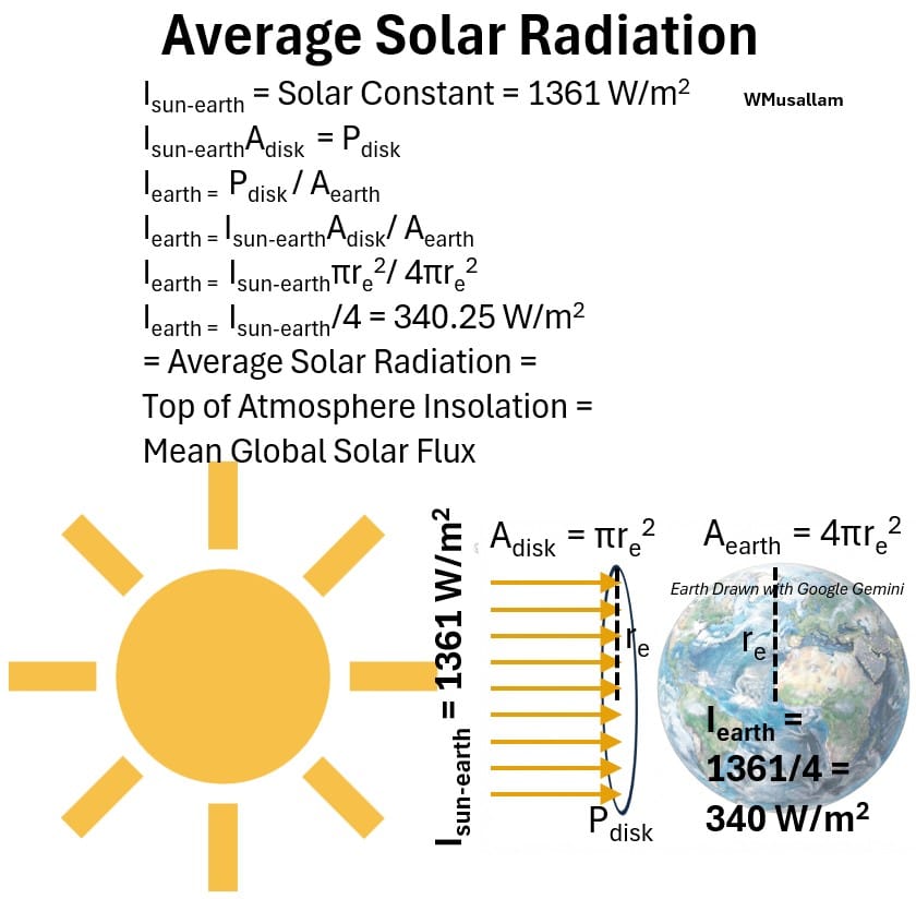
From the perspective of the Sun, the rays hitting the Earth are hitting a circular area with a radius equal to the Earth’s radius .
Imagine the light is a layer of paint spread out over this 2D Earth circle of area re.
- The total power in this circular area, Pdisk , on average, has to cover the whole surface area of the Earth.
- So, using the paint analogy, applying that layer of paint around the full sphere of Earth will thin it out or dilute it.
- So Iearth , the average solar radiation at Earth will be = Pdisk /area of the Earth
Let’s do the math and see what kind of expression we can get for Iearth
We know that,
Isun-earth = Solar Constant = 1361 W/m2
We can express the power of the Sun rays on that disk, in SI units of Watts, as Pdisk . This can be expressed as
- Isun-earthAdisk = Pdisk
where Adisk is the area of the circle with radius re (the radius of the Earth) that the light rays are hitting:
- Adisk = πr2e
The Sun’s power in Pdisk must be applied across the whole surface area of the Earth.
- Iearth = Pdisk / Aearth
Where
- Iearth = Average Solar Radiation = Top of Atmosphere Insolation = Mean Global Solar Flux
- Aearth = Surface area of the Earth as a sphere: 4πr2e
Substitute equations 1 and 2 and the expression for Aearth into equation 3 to get.
- Iearth = Isun-earthAdisk / Aearth = Isun-earth πr2e /4πr2e
This simplifies to
(ES3) Iearth = Isun-earth / 4 = 1361/4 = 340 W/m2; Average Solar Radiation = Top of Atmosphere Insolation = Mean Global Solar Flux Density
Solar Radiation Attenuation (Depletion, Extinction)
Of course, because of Earth’s rotation, for roughly half the time, there is no sunlight.
When there is sunlight, it hits the Earth and travels down to the surface, but, it does not arrive with 100 percent of its original power.
Along the way, the Earth’s atmosphere filters a large portion of the total solar energy by reflection, scattering, and absorption.
Solar radiation attenuation refers to the gradual reduction in the intensity of electromagnetic radiation as it passes through a medium like the atmosphere.
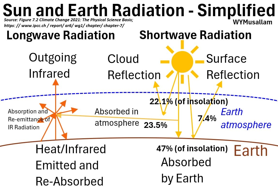
In the picture below, I show the major forms of solar radiation attenuation (reduction, removal).
I also show for completeness that Earth absorbs some solar radiation and emits infrared radiation, which then gets absorbed and re-emitted (with a portion of it eventually escaping the atmosphere into space).
This IR absorption and re-emittance is the integral mechanism of global warming which I cover in this article (Global Warming Primer).
Picture: Solar Radiation Attenuation
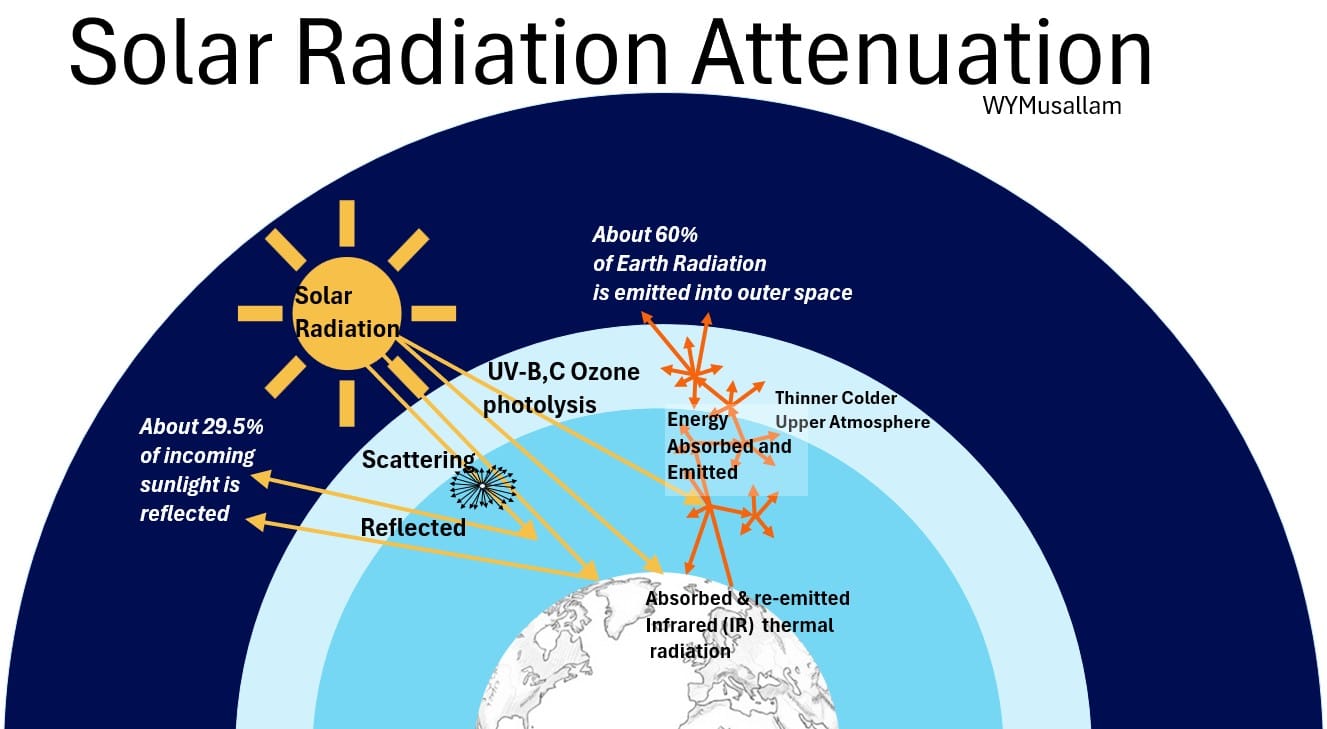
We can describe four different types of attenuation:
1. Upper Atmospheric Reaction with Ozone (UV Absorption)
The stratosphere effectively filters out the most dangerous components of solar radiation through dedicated photolytic destruction.
- UV-C is 100% absorbed and destroyed as high-energy photons break apart molecular oxygen and ozone, while UV-B is 90% to 95% removed by ozone absorption.
- The byproduct of UV-C photolysis on molecular oxygen (O2) is two free oxygen atoms (O + O), whereas the photolysis of ozone (O3) by UV-B and UV-C yields one oxygen molecule (O2) and one free oxygen atom (O).
- This protects life on Earth from harmful radiation while creating distinct temperature layers in the upper atmosphere (i.e. , photolysis produces heat).
2. Infrared (IR) Absorption
- Some solar radiation will be directly absorbed in the atmosphere.
- Mid-to-far infrared wavelengths, primarily associated with thermal energy, are absorbed by greenhouse gases as sunlight travels lower into the atmosphere.
- Molecules like water vapor (H2O), carbon dioxide (CO2), and methane (CH4) possess chemical bonds that resonate with these specific infrared frequencies.
- Upon absorbing an infrared photon, the molecule becomes excited and temporarily stores that energy before re-emitting a new infrared photon in a random direction, which traps and circulates heat within the Earth system.
3. Reflection
- A significant fraction of incoming solar radiation is bounced directly back out into space before it can be absorbed.
- This is driven by Earth’s albedo (reflectivity).
- Bright surfaces like thick cloud tops, snow, and ice reflect a massive percentage of incoming shortwave radiation away from the planet, whereas dark surfaces (like oceans or dense forests) absorb it.
4. Scattering
- Incoming sunlight collides with gas molecules, dust, and aerosols, which deflect the photons in random directions without absorbing them.
- This is split into Rayleigh scattering (air molecules scattering shorter blue wavelengths, giving us a blue sky)
- and Mie scattering (larger dust/smoke particles scattering all visible wavelengths more equally, causing hazy or white skies).
- It turns a portion of direct sunlight into diffuse, scattered light.
Rayleigh Scattering
Consider the picture below showing
- incident sunlight hitting a particle (or molecule),
- which scatters the light in many directions,
- and a viewer who sees the scattered radiation at some angle θs.
Picture: Rayleigh Scattering
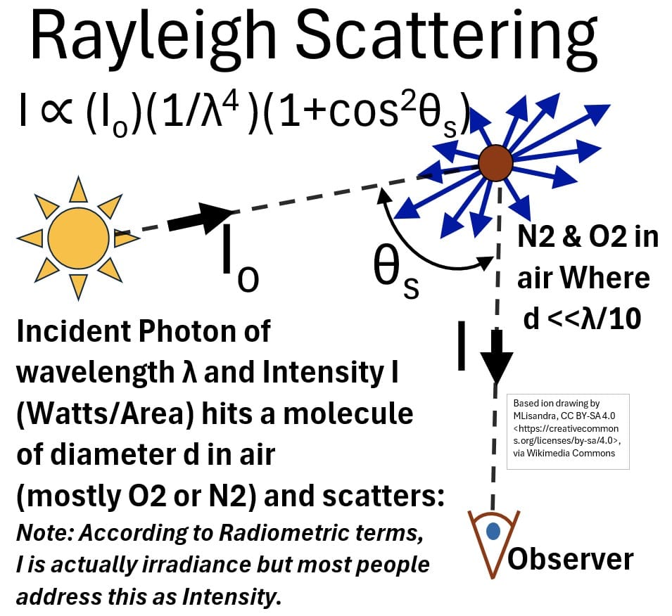
- This “Rayleigh Scattering” drawing displays the governing mathematical relationship:
(SA1) I ∝ (Io)(1/λ4)(1+cos2θs) ; Governing Relationship for Rayleigh Scattering
- It illustrates an incident photon with wavelength λ and initial intensity Io (in W/m2)
- striking a small air molecule (such as N2 or O2) with a diameter d much smaller than the wavelength (d <<λ/10),
- causing the light to scatter in multiple directions.
- The incoming ray from the sun interacts with the molecule at a scattering angle , θs , dispersing blue-directional arrows outward, while a scattered ray (I) travels downward to an observer.
- Note that while I is commonly called “Intensity,” radiometrically speaking, it actually represents irradiance (see Appendix 1 for the radiometrically correct light “type” terminology).
Mie Scattering
The diagram below compares two main types of atmospheric light scattering side-by-side:
- Rayleigh Scattering on the left and
- Mie Scattering on the right.
Picture: Rayleigh vs Mie Scattering
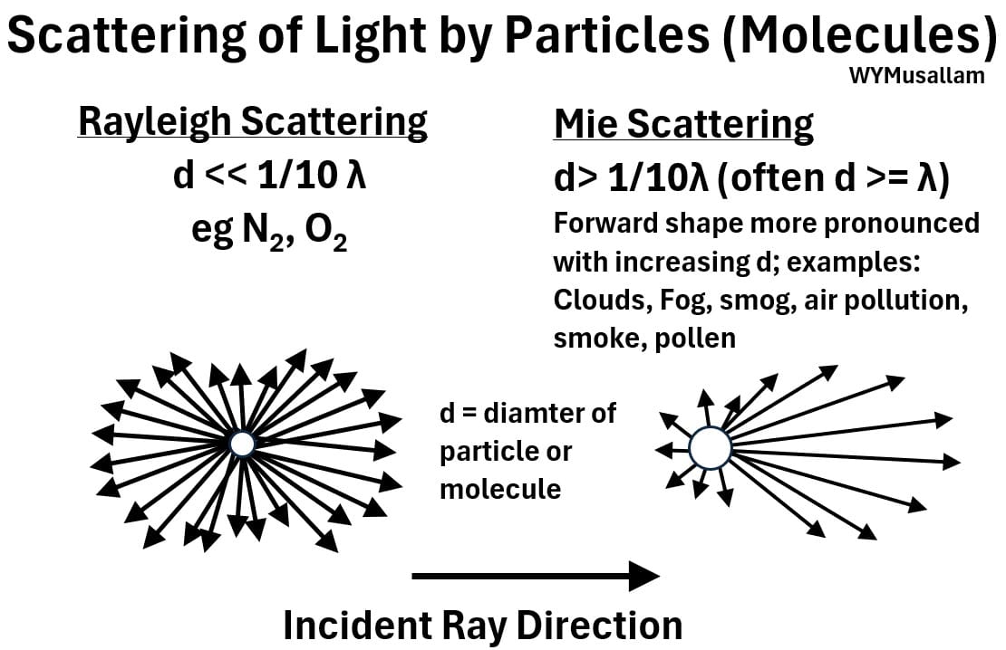
Left Side: Rayleigh Scattering
- Rayleigh Scattering occurs when d is much less than 1/10 λ
- So Gas molecules such as nitrogen (N2) and oxygen (O2) fit the bill.
- The left picture shows a central small particle surrounded by radiation scattering outward in all directions.
- The pattern forms a symmetric, nearly uniform 360-degree distribution, illustrating that light is scattered roughly equally backward, forward, and sideways.
Right Side: Mie Scattering
- Mie Scattering occurs when the particle diameter is larger than one-tenth of the wavelength, often equal to or larger than the wavelength itself.
- Examples of Mie Scatterers: Clouds, fog, smog, air pollution, smoke, and pollen.
- The right picture shows a scattering pattern with arrows pointing outward, but the pattern is strongly asymmetric.
- The majority of longer, prominent arrows extend to the right (forward direction along the incident light path), while much shorter arrows extend backward and sideways, demonstrating strong forward scattering
Solar Radiation Spectrum at Earth
The chart below plots solar irradiance (W/m2 /nm wavelength) against wavelengths ranging from 250 to 2500 nm, comparing sunlight at the top of the atmosphere to sunlight at sea level.
Picture: Solar Radiation Spectrum On Earth (Cloud Free; Top of Atmosphere and at Sea Level)
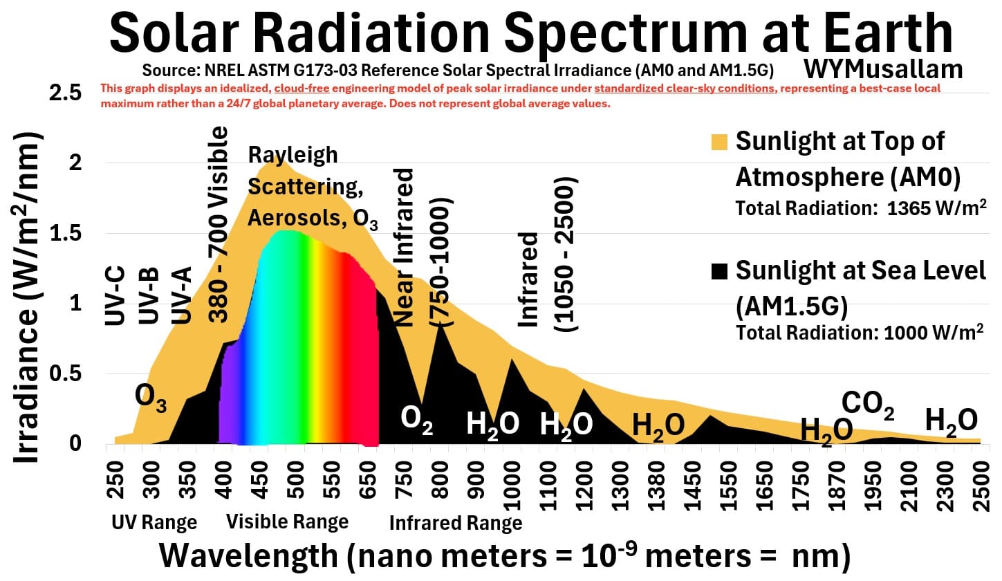
- Ozone: In the ultraviolet range (100–400 nm), ozone (O3) and molecular oxygen heavily filter out high-energy UV-C (completely) and UV-B (roughly 90–99%),
- creating a massive drop between top-of-atmosphere baseline and sea-level irradiance in those bands.
- Longer-wavelength UV-A (315–400 nm) is largely unabsorbed by ozone, allowing almost all of it to penetrate down to the surface.
- Scattering: Across the visible and near-IR spectrum (roughly 380–700 nm and the upper curve envelope), attenuation is driven by Rayleigh scattering and aerosols, which scatter short wavelengths away from a direct path to the surface.
- Absorption: In the infrared range (750–2500 nm), a series of deep troughs and dips reveals where infrared radiation is strongly absorbed by atmospheric gases, specifically oxygen (O2), carbon dioxide (CO2), and multiple water vapor (H2O) bands.
How Much Solar Radiation Gets to the Earth?
Based on the provided clear-sky engineering model (represented by the chart above), approximately 70% of incoming solar radiation reaches the Earth’s surface at sea level (1000 W/m2 out of the 1365 W/m2 top-of-atmosphere baseline).
But in reality only about 48% of incoming solar energy actually reaches the surface globally.
This discrepancy occurs because the chart above depicts an idealized, cloud-free local maximum under standardized clear-sky conditions rather than a true 24/7 global planetary average.
- Real-world global energy balances must factor in widespread cloud cover, day-night cycles, seasonal variations, and varying solar zenith angles across the entire planet, all of which substantially reduce long-term average surface insolation.
You can read more about the Earth’s average energy balance in my post titled: Global Warming Primer.
Picture: Solar Insolation and Amount Reaching Earth
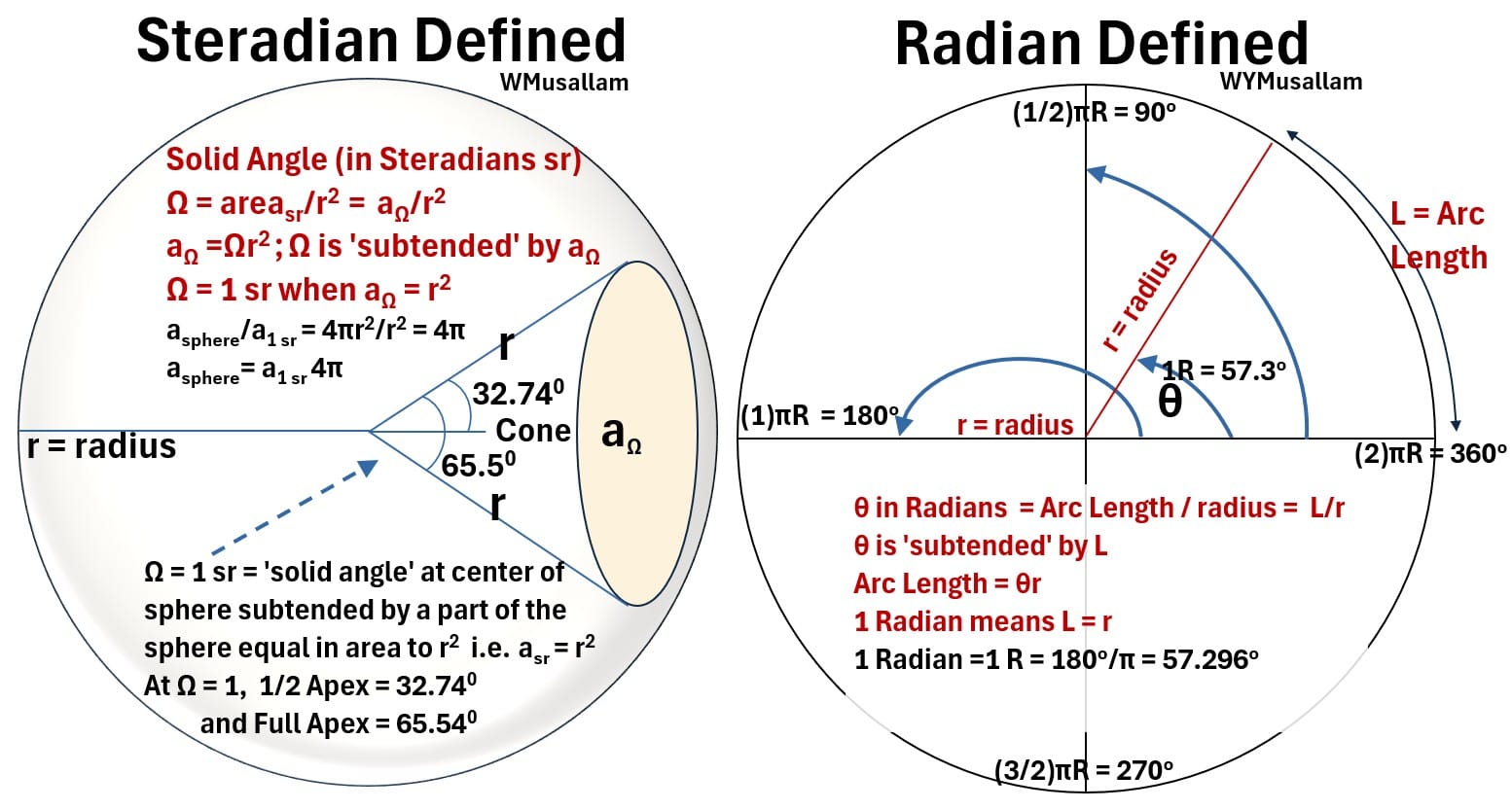
Radian and Steradian Defined
Radian (R) Defined
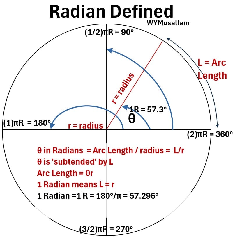
Consider the picture below of a circle of radius r.
Picture: Radian Defined on a Circle of Radius r
Radian Definition
(RS1) θ (in radians R) = L / r ; Radian Definition
(RS2) Arc Length L = θr ; Radian Definition
Understanding the Word ‘Subtend’
- In geometry, to subtend means to “extend under” or “span across.”
- This means the curved arc along the edge of the circle forms the outer boundary that opens up to create that specific angle at the center.
1 Radian Defined
When the curved arc equals the straight-line radius of the circle (L = r), the angle subtended at the center is exactly 1 radian (approximately 57.3 degrees).
The diagram maps key coordinate thresholds around the circle, showing that a straight line (180 degrees) spans π radians, while a full rotation (360 degrees) spans 2π radians.
Steradian (sr) Defined
Consider the picture below of a sphere with radius r.
Picture: Steradian Defined on a Sphere of Radius r
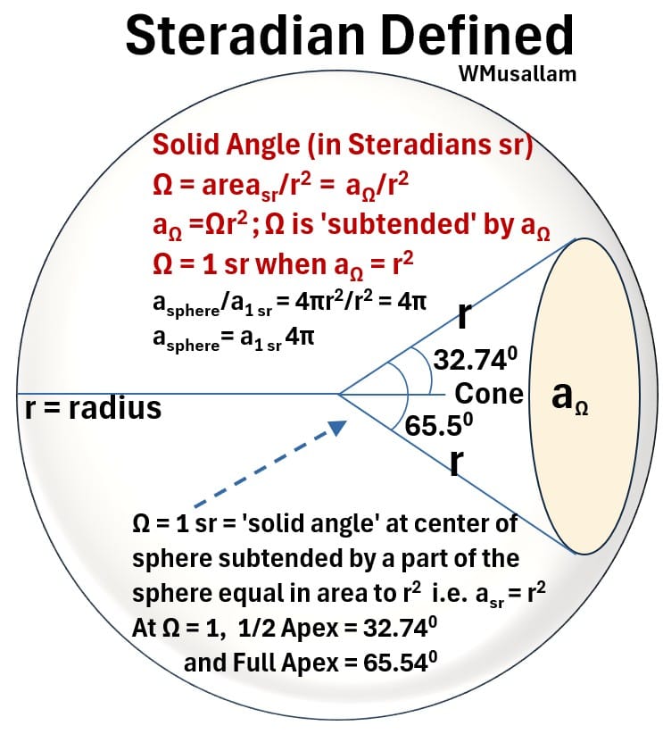
A steradian (sr) is the standard unit of measurement for a three-dimensional angle, also known as a solid angle (just means we are dealing with 3D shapes).
- Just as a regular radian measures an angle along a flat 2D circle, a steradian measures a cone-like angle spreading out through 3D space.
Imagine standing inside the exact center of a hollow sphere with a radius of 1 meter.
- If you project a beam of light from the center onto the inside wall of that sphere, it will trace out a circular patch.
- If you expand that beam until the illuminated patch on the wall covers an area of exactly 1 square meter, the angle of that light cone is exactly 1 steradian.
- If the patch is a circle, then the cone angular spread is defined by the steradian i.e. , the steradian is an angular spread factor
- For example, 1 steradian defines a cone whose half and full apex angular spreads are 32.74 and 65.5 degrees respectively
The Solid Angle
(RS3) Ω (in Steradians sr) = aΩ/r² ; Solid Angle (Steradian) Definition
Understanding ‘Subtended’ in 3D
- In three dimensions, this means the bounded 2D area patch on the outside of the sphere
- opens inward to project a cone that forms a specific 3D space angle at the absolute center.
- A solid angle is equal to 1 steradian (1 sr) when the surface area of the patch equals the radius squared aΩ = r²).
- At this exact threshold, the projecting cone features a half-apex angle of 32.74 degrees and a total full-apex opening angle of 65.54 degrees.
Total Sphere Space
Because the total surface area of a whole sphere is 4π r², dividing by r² shows that
- a complete sphere encompasses a total solid angle of exactly 4π steradians or about 12.57 steradians.
Comparison of Steradian and Radian
Think of a steradian as simply the 3D version of a radian.
- While a flat radian (R) is measured by tracing a curved line along the edge of a circle (θ = L / r or L = θ r),
- a volumetric steradian (sr) is measured by tracing a patch of surface area over the shape of a sphere (Ω = A / r² or A =Ωr² ).
An easy way to visualize the scale difference is to look at a complete shape:
- a flat circle wraps around exactly 2π radians,
- while a full 3D sphere opens up to encompass a total of 4π steradians.
Picture: Steradian and Radian Compared
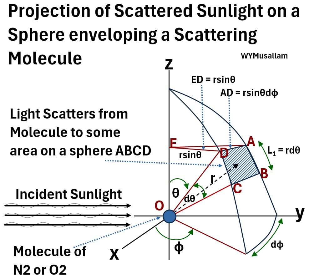
Projection of Scattered Sunlight on a Sphere Enveloping a Scattering Molecule
Consider the picture below of an atmospheric molecule (e.g. O₂ or N₂) which is receiving sunlight and scattering it outwards.
Picture: Projection of Scattered Sunlight on a Sphere enveloping a Scattering Molecule
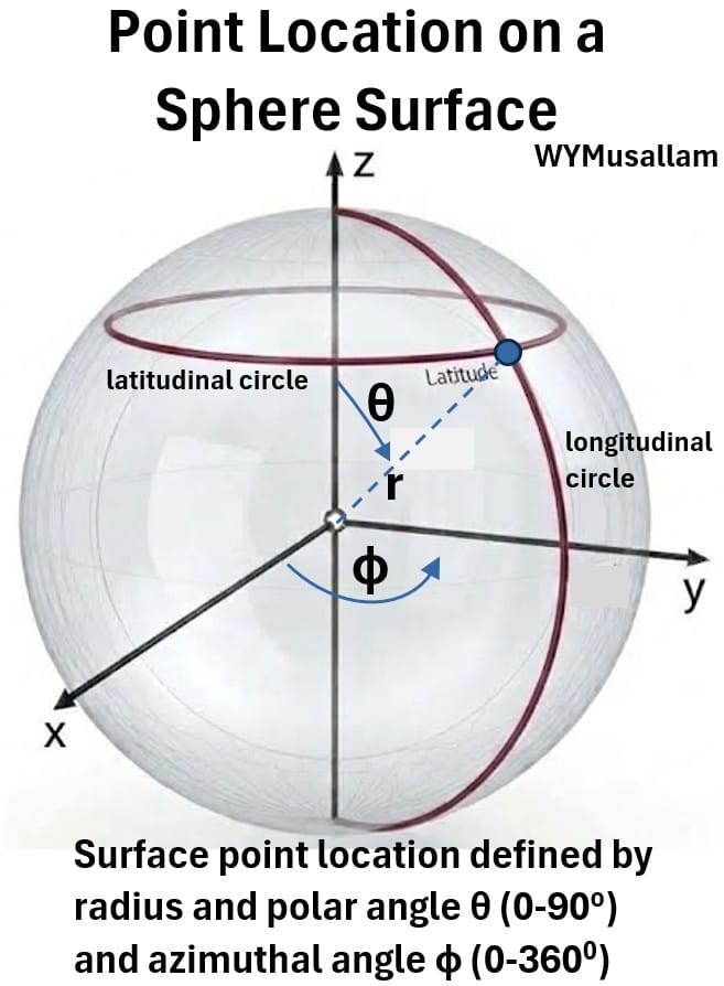
Location of a Point on a Spherical Surface
- r (Radius): The fixed distance from the center of the sphere.
- Two angular variables, θ and Φ : The directional angles that pinpoint the exact position on the surface.
The Polar Angle (θ / Theta)
- This determines the point’s co-latitude (vertical height; see note). An easy way to remember the word latitude is the direction of the “long side” of your mouth when you say the word.
- It measures the angle downward from the positive vertical Z-axis (0° at the north pole to 180° at the south pole).
- This angle defines a horizontal (latitudinal) circle (see the picture below also).
- A changing angle results in vertical movement of that horizontal circle.
Note: Technically, θ measures co-latitude (distance from the North Pole) rather than direct latitude.
- Latitude measures angle from the equator (-90° +90°), whereas colatitude measures angle from the North Pole (0° to $180°).
The Azimuthal Angle (Φ / Phi):
- This determines the point’s longitude. An easy way to remember the word is the direction of the “long side” of your mouth when you say the word.
- It measures the horizontal rotation around the XY-plane (from 0° to 360°).
- The azimuthal angle defines the exact location the point sits in the horizontal circle defined by the polar angle (see the picture below).
In summary, we can exactly define the location of a point anywhere on a surface of a sphere if we know the radius r, θ and Φ.
- the polar angle θ defines the vertical location of a horizontal circle on a sphere.
- the azimuthal angle Φ locates a point on the horizontal circle defined by the polar angle.
Picture: Point Location on a Spherical Surface
The Shaded Area Element (ABCD)
Picture: Solid Angle Expressed in Spherical Coordinates
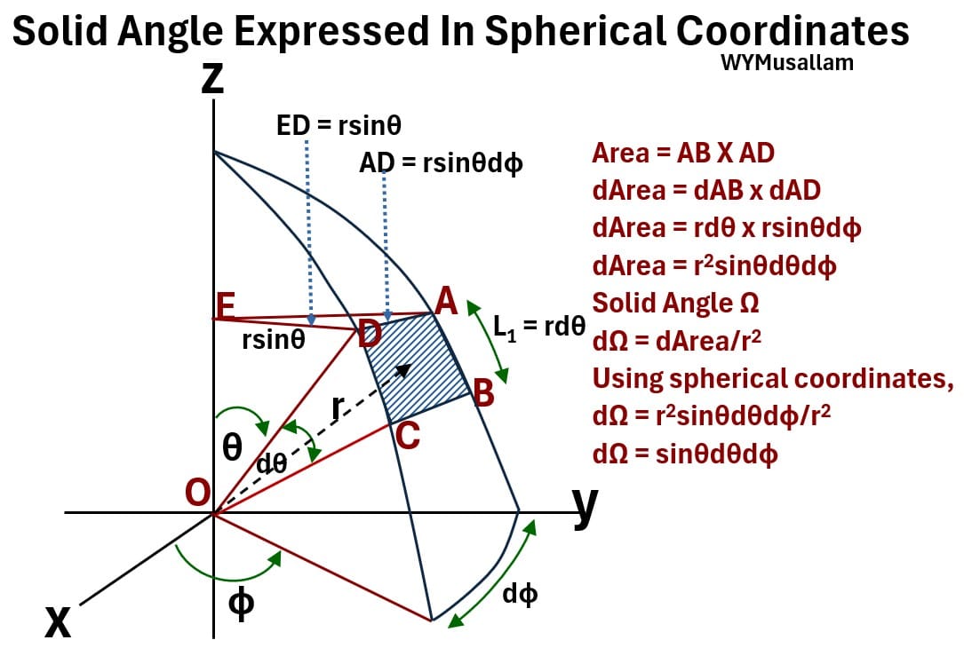
The Vertical Side (AB = L1 = r dθ)
We know that in a circle, the arc length that subtends an angle θ will equal rθ.
- (RS2) Arc Length L = θr
So, as the polar angle tilts downward by a tiny differential amount (dθ), it sweeps out a straight physical arc length along a north-south line of longitude equal to:
- (PS1) AB = L1 = r dθ
The Horizontal Side (AD = r sinθ dϕ):
- From the picture above and basic trigonometry, we know that sinθ = opposite/adjacent = ED/r
- So ED = r sinθ, which is the effective radius of the horizontal circle the point lies on.
- Using the definition of the circle arc length again (equation RS2) and assuming a tiny differential change in Φ (dΦ),
- (PS2) AD = effective radius x dΦ = ED x dΦ = r sinθdΦ.
- So a tiny horizontal rotation (dΦ) sweeps out a physical arc length equal to r sinθ dΦ.
Area of ABCD
- (PS3) Area = dA = AB x AD = (r dθ) × (r sinθ dΦ) = r² sinθ dθ dΦ
Incorporate the Definition of a Solid Angle
- (RS3) Ω (in Steradians sr) = aΩ /r²
- Ωr² = aΩ
For an infinitesimal area da,
- dΩr² = daΩ
Substitute this expression into equation PS3 (the area equation for ABCD), where aΩ = A:
- (PS4) dΩr² = dA
- dA = d(AB x AD) = dΩr² = (r dθ) × (r sinθ dΦ) = r² sinθ dθ dΦ
(PS5) dΩ = sinθ dθ dΦ ; Solid Angle in Spherical Coordinates
This is the equation that calculates the exact size of a tiny 3D window (a solid angle element) on the surface of a sphere.
It tells you how a small patch changes in size as you move around a three-dimensional ball.
- dΩ: This is the tiny piece of 3D angular space (the solid angle) that you are trying to measure.
- Think of it as the opening size of a cone projecting from the center of the sphere.
- dθ: This is a tiny step moving north-to-south.
- dΦ: This is a tiny step rotating east-to-west.
- The sinθ Factor: It acts as a scaling corrector—it shrinks the calculated area down near the top and bottom poles
Differential and Total Scattering Cross Section
- This gives us the angular “size” of the window ABCD as seen directly from the molecule’s perspective,
- completely independent of how large or small the imaginary sphere is.
- (PS5) dΩ = sinθ dθ dΦ ; Solid Angle in Spherical Coordinates
Now we’ll define the incoming and outgoing light intensity.
Incoming Versus Outgoing Light
- Incident Intensity (Io): The power (energy per second) of the incoming sunlight striking a unit area (in units of W/m²)
- Outgoing Intensity (I): The power (energy per second) of the outgoing scattered light leaving a unit area (in units of W/m²)
- Scattered Power (P): The actual amount of light energy per second (in units of Watts) captured inside the area ABCD.
- Scattered Power (differential) = dP = Outgoing Intensity (in W/m2) x Area of Patch = (I)(dA)
- (DS1) dP = IdA ; a differential change in scattering power P.
note: technically, according to radiometric terminology (See Appendix 1 ), I is irradiance and not intensity, but intensity is commonly used.
We are ready to compute the differential scattering cross section.
The Differential Scattering Cross-Section
- (DS2) dσ (units of area) = d(Scattered Power)/Incident Intensity = dP/Io
Substitute equation DS1 (dP = IdA) into DS2:
- (DS3) dσ = (I)(dA)/Io
Substitute equation (PS4) dA = dΩr² into (DS3):
- dσ = (I)(dΩr²)/Io
- (DS4) dσ = (I/Io)(r²)(dΩ)
substitute the solid angle definition equation (PS5) dΩ = sinθ dθ dΦ into (DS4):
(DS5) dσ = (I/Io)(r²)(sinθ dθ dΦ) ; Differential Scattering Cross Section
Total Scattering Cross Section
To compute the total scattering cross-section, you perform a double integration of the differential cross-section over all angles of a full sphere,
- using boundaries from 0 to 2π for the azimuthal (horizontal) angle (Φ)
- and 0 to π for the polar (vertical angle θ)
Note, we are essentially expanding that area to cover the full sphere area. We can’t just use the equation of the surface area of a sphere because I is not constant.
So we have to solve a double integration of equation DS5:
(DS6) σ = ∫o to 2π∫o to πdσ , where we integrate through the ranges Φ = 0 to 2π (i.e. , 0 – 3600) and θ = 0 to π (i.e. , 0 – 1800)
Substitute equation (DS5) dσ = (I/Io)(r²)(sinθ dθ dΦ) into (DS6):
(DS7) σ = ∫o to 2π∫o to π(I/Io)(r²)(sinθ dθ dΦ)
move dΦ to its dedicated integral
(DS8) σ = ∫o to 2π dΦ ∫o to π(I/Io)(r²)(sinθ dθ)
What is this and how do we solve it?
Explaining and Solving the Double Integral
Just as a single integral accumulates a one-dimensional function over a one-dimensional interval (such as the area under a curve), this double integral accumulates a two-dimensional scattering intensity function over the 2D spherical surface of a target, calculating the total effective cross-sectional area σ by summing up scattered particles or light across all possible angular directions.
When you look at a double integral expression like this:
(DS8) σ = ∫o to 2π dΦ ∫o to π(I/Io)(r²)(sinθ dθ)
The easiest way to solve it is to work from the inside out
- Step 1: Solve the Inside Integral First
- Focus only on the inner integral sign and its matching variable at the end (in our case, dθ).
- Treat every other variable in the problem (like Φ) as if it is just a plain, unchanging number.
- Do your normal calculus integration steps on θ, plug in your upper and lower boundaries (0 and π), and get your result.
- Step 2: Solve the Outside Integral Second
- Take the answer you just got from Step 1 and place it inside the remaining outer integral sign, which matches the final variable (dΦ).
- Now, run your second integration step using your new variable, plug in your remaining boundaries (0 and 2π), and you have your final total value.
- If the math functions inside the integrals are completely separated i.e. , the θ terms and the Φ terms are multiplied together rather than added,
- you can split the double integral completely apart into two independent single integrals.
- You simply calculate the answer to both individual pieces separately and multiply the two results together at the end!
Solving the Integral: Setting Up the Substitution
- Recall out general relationship for Rayleigh Scattering in equation SA1 :
- (SA1) I ∝ (Io)(1/λ⁴ )(1+cos²θ)
- A more accurate equation is shown below.
- The intensity of light scattered by any one of the small spheres of radius r (or diameter 2r) and refractive index n (see Appendix 2) from a beam of unpolarized light of wavelength λ and intensity Io is given by
(DS9) I / Io = [ (1 + cos²θ) / (2r²) ] × (2π / λ)⁴ × [ (n² – 1) / (n² + 2) ]² × (d / 2)⁶ ; Rayleigh Equation
- where r is the observer’s distance to the particle and θ is the scattering angle
Note: Almost all common light sources—like the sun, standard incandescent light bulbs, and candles—emit unpolarized light. Because its electric fields are randomly pointing in all directions around the beam’s axis, unpolarized light has no “up-down” or “left-right” bias.
- (DS10) C = (1 / 2) × (2π / λ)⁴ × [ (n² – 1) / (n² + 2) ]² × (d / 2)⁶
The intensity ratio equation (DS9) now looks a lot less cluttered when we substitute in C.
- (DS11) I / I0 = C × (1 + cos²θ) / r²
Solving the Integral: Plugging I/I0 into the Total Cross-Section Integral
- (DS8) σ = ∫0 to 2π dΦ ∫0 to π (I / Io) × r² × sinθ dθ
- (DS12) σ = ∫0 to 2πdΦ ∫0 to π[ C × (1 + cos²θ) / r² ] × r² × sinθ dθ
- (DS13) σ =C ∫0 to 2πdΦ ∫0 to π(1 + cos²θ)sinθ dθ
Part 1: Solving the Integral: The Φ Integral (Horizontal Rotation)
- (DS14) ∫0 to 2πdΦ = 2π
Part 2: Solving the Integral: The θ Integral (Vertical Angle)
- Let u = cosθ
- Then the derivative is du = -sinθ dθ, which means sinθ dθ = -du
- Change the integration boundaries using u = cosθ
- When θ = 0, u = cos(0) = 1
- When θ = π, u = cos(π) = -1
- Substitute u and -du into the integral
- ∫1 to -1 (1 + u²) (-du)
- Flip the boundaries to remove the negative sign
- ∫-1 to 1(1 + u²) (-du) = ∫(-1 to 1) (1 + u²) du
- Find the antiderivative
- ∫-1 to 1(1 + u²) du = [ u + (u³ / 3) ] evaluated from -1 to 1
- Plug in the upper boundary (1) and subtract the lower boundary (-1)
- (DS15) ∫-1 to 1(1 + u²) du = [ 1 + (1/3) ] – [ -1 + (-1/3) ] = [ 4/3 ] – [ -4/3 ] = 8/3
Part 3: Solving the Integral: Combining the Final Terms
- σ = C × 2π × (8/3)
- (DS16) σ = (16π / 3) × C
- (DS17) σ = (16π / 3) × (1 / 2) × (2π / λ)⁴ × [ (n² – 1) / (n² + 2) ]² × (d / 2)⁶
- (DS18) σ = (8π / 3) × (2π / λ)⁴ × [ (n² – 1) / (n² + 2) ]² × (d / 2)⁶
- (DS19): (2π / λ)⁴ = (2⁴ × π⁴) / λ⁴ = 16π⁴ / λ⁴
Expand the molecular diameter term:
- (DS20): (d / 2)⁶ = d⁶ / 2⁶ = d⁶ / 64
- (DS21) σ = (8π / 3) × (16π⁴ / λ⁴) × [ (n² – 1) / (n² + 2) ]² × (d⁶ / 64)
- Numerator coefficients: 8 × 16 = 128
- Denominator coefficients: 3 × 64 = 192
- Combining the numbers: 128 / 192 = 2 / 3
- Combining the π terms: π × π⁴ = π⁵
- (DS22) σ = (2/3) × (π⁵ / λ⁴) × d⁶ × [ (n² – 1) / (n² + 2) ]²
(DS23) σ = [ (2π⁵ d⁶) / (3λ⁴) ] × [ (n² – 1) / (n² + 2) ]² ; V1: Rayleigh Total Scattering Cross-Section formula – particle diameter based
Expressed in terms of r instead of d (d = 2r for particle) and using exponent rules:
- σ = [ (2π⁵ (2r)⁶) / (3λ⁴) ] × [ (n² – 1) / (n² + 2) ]²
- σ = [ (2π⁵ 2⁶r⁶) / (3λ⁴) ] × [ (n² – 1) / (n² + 2) ]²
- σ = [ (π⁵21 2⁶r⁶) / (3λ⁴) ] × [ (n² – 1) / (n² + 2) ]²
- σ = [ (π⁵23 24r⁶) / (3λ⁴) ] × [ (n² – 1) / (n² + 2) ]²
- σ = [ (π⁵23 24r⁶) / (3λ⁴) ] × [ (n² – 1) / (n² + 2) ]²
- σ = [ (π1π42324r⁶) / (3λ⁴) ] × [ (n² – 1) / (n² + 2) ]²
- σ = [ (π1π42324r⁶) / (3λ⁴) ] × [ (n² – 1) / (n² + 2) ]²
- σ = [ 1/3(23π1π4)(24/λ⁴) ] × [ (n² – 1) / (n² + 2) ]²× r⁶
- σ = (8π/3)(24π4/λ⁴) × [ (n² – 1) / (n² + 2) ]² × r⁶
So DS23 can also be expressed as
(DS24) σ = (8π/3)(2π/λ)4 × [(n² – 1)/(n² + 2)]² × r⁶; V2: Rayleigh Total Scattering Cross-Section formula – particle radius based
This equation tells us that in Rayleigh scattering:
- the total amount of scattered light is inversely proportional to the fourth power of the wavelength (1/λ⁴).
- Les assume we have blue light at 450nm being scattered and red light at 700 nm being scattered.
- σblue;450nm /σred;700nm = (λred;700nm/λblue;450nm)4 = (700/450)4 = 5.8
- So Blue Light at 450 nm scatters about 6x as much as red light.
Why the sky is blue during the day
During the middle of the day, sunlight enters the atmosphere from overhead and takes a short, direct path to your eyes.
- The steep 1/λ⁴ drop-off means shorter blue wavelengths interact with air molecules much more aggressively than longer wavelengths, scattering blue light in every direction across the sky while red light passes through relatively undisturbed.
Why we see orange/red at sunsets and sunrises
At sunrise and sunset, when the sun is low on the horizon, sunlight must travel through a much thicker layer of the atmosphere to reach you.
As shown in the picture below, the distance of sunlight to an observer at sunrise Lmax can be 38x further than it is when the sun is straight overhead at Lmin.
Picture: Solar Zenith Angle
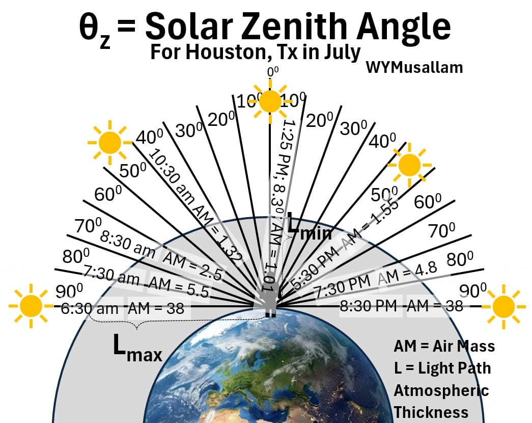
- Because of this longer path, almost all of the blue light is scattered away in other directions long before it reaches your line of sight.
- What remains to pass straight through this heavy atmospheric filter are the longer, less easily scattered red and orange wavelengths.
Picture: Blue Scatter Above But Only Orange/Red Gets Through along the Horizon
Why do we See Blue more than Purple?
The reason we see blue instead of purple when looking at the sky or a rainbow comes down to two main factors:
- solar emission output and
- human eye photoreceptor sensitivity.
While Rayleigh scattering dictates that shorter wavelengths scatter much more efficiently than longer ones (scaling inversely with the fourth power of wavelength, 1/λ⁴, two things happen at the extreme short end of the visible spectrum:
- The Sun emits less violet light: The sun’s radiation curve drops off significantly in the ultraviolet and deep violet range compared to its peak output in the blue and green regions.
Picture: Solar Spectrum at Top of Earth Atmosphere and at Sea Level
- Human color perception: Our eyes have three types of color-sensing cone cells (red, green, and blue).
- Violet light stimulates both the short-wavelength (blue) cones and—to a lesser extent—the long-wavelength (red) cones.
- Combined with our lower sensitivity to light wavelengths below 450 nm, our brain perceives the mix of scattered short-wavelength light predominantly as sky-blue rather than pure violet.
Percent Scattering Equations
If you do a web search on “Rayleigh Scattering” you will probably find the picture below.
Picture: Percent Scattering of Direct Sunlight (Rayleigh Scattering)
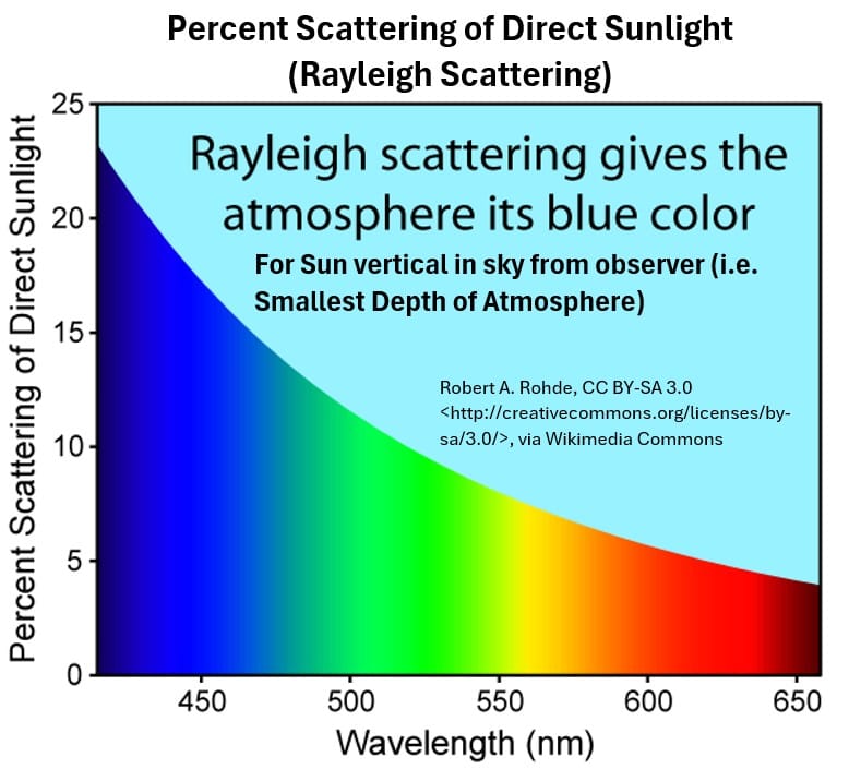
- Vertical columns of color allow you to match wavelength to color.
- So this says that about 23% of very short wavelength visible light (400 nm) is scattered
- while about 4% of 650 nm red light is scattered.
Note that this graph assumes a straight overhead position of the sun (i.e. , sun rays are going through the narrowest distance of atmosphere to the earth).
It would be nice to see how the curve changes with changing position of the sun in the sky.
In order to generate a multi-curve % scattering plot for various positions of the sun in the atmosphere, we need a few more equations.
1. Rayleigh Scattering Coefficient (β)
The Rayleigh Scattering Coefficient, β, Measures the fraction of light intensity lost to scattering per unit distance as a beam travels through a gas.
It’s unit of measure is 1/m (or m-1 = inverse meters)
- (SE1) β = N · σ
Substitute in our expression for σ (equation SP8):
- (SE2) β = N (24π3 )/( λ4N2) × [(n² – 1)/(n² + 2)]² × Fk
Combine the N terms:
(SE3) β = (24π3)/( λ4N) × [(n² – 1)/(n² + 2)]² × Fk ; Rayleigh Scattering Coefficient
- N: Molecular density
- n: Refractive index (see Appendix 2)
- [(n² – 1)/(n² + 2)]² : a term that accounts for polarizability (see Appendix 2)
- Fk: King correction factor
2. The Beer-Lambert Law for Transmission
(SE4) T = exp(-τ); Beer-Lambert Law for Transmission
- τ is the total optical depth of the atmosphere at wavelength λ.
- T = Transmittance
- (SE5) A = εcl.
- A : Absorbance
- ɛ: Attenuation Coefficient: Molar Absorption Coefficient
- C: Molar Concentration
- L: Optical Path Length
- (SE6) A = -ln(T).
- (SE7) – ln(T) = εcl
- (SE8) τ = εcl
- (SE9) – ln(T) = τ
- (SE10) ln(T) = – τ
Take the exponent of both sides of equation SE9:
- (SE11) T = exp(- τ)
(SE12) τ = β × H × AM ; Optical Depth
- H: Scale height of the atmosphere (~ 8,400 meters).
- AM: The Kasten-Young airmass formula, which depends on the solar zenith angle (θz).
4. Kasten-Young Airmass Formula (AM)
(SE13) AM = 1 / [cos(θz) + 0.50572 × (96.07995 – θz) – 1.6364]
Note in the picture below how the AM values are highest (AM = 38) at sunrise and sunset when L is at Lmax (indicating “thickness of atmosphere”).
This coincides with sunrise and sunset zenith angles θz of 90 degrees.
Picture: Solar Zenith Angle and AM Values for Houston Texas in July
Let’s use these four equations to generate % scattering curves for visible light at different AM values (i.e. , different locations in the sky relative to an observer).
Atmospheric Light Scattering Calculations
Example Calculation To Compute Percent Scattering of Sunlight
- Purple/Blue light at λ=400 nm
- for both AM=1.96 (about 9 am in Houston in July) and AM=3.26 (about 8am in Houston in July).
Known Values
- Wavelength λ: 400 nm=4.0×10⁻⁷ m
- AM=1.96 and AM=3.26
- Molecular Number Density (N): 2.547×1025 molecules/m3
- Effective Scale Height (H): 8,400 m
- King Correction Factor (Fk): 1.048
Compute the n term in the equation SE3 (Rayleigh Scattering Coefficient).
- Assume a refractive index of air of n = 1.000278, which is the standard value for air specifically at a wavelength of 400 nm.
- n doesn’t change significantly with visible wavelength so we will keep it constant.
- ((n2-1)/(n2+2))2 ≈ 3.552×10⁻⁸
Compute the Rayleigh Scattering Coefficient β (Equation SE3):
- (SE3) β =(24π3)/(λ4 N) × ((n2-1)/(n2+2))2 × Fk
- Denominator term (λ4 N): (4.0×10⁻⁷)4 × (2.547×1025) = (2.56×10-26)×(2.547×1025) = 0.65203 m
- β =(744.38/0.65203)×(3.552×10-8) × 1.048
- β = 4.25×10⁻⁵ m-1
Calculate optical depth τ for AM = 1.96.
- (SE12) τ = β×H×AM
- τ = (4.25×10⁻⁵ m-1)⋅(8,400 m ) × 1.96
- τ = 0.700
Compute the Beer-Lambert Transmission (T) for AM = 1.96.
- (SE4) T = exp(-τ)
- T = e-.7 ≈ 0.4966 (49.7% reaches the surface )
Compute Percent Blue Light Scattered for AM = 1.96.
- Scattered = (1 – 0.4966)×100 = 50.3%
Calculate τ for AM = 3.26.
- τ = β x H x AM
- τ = 4.25×10⁻⁵ m-1 x 8,400 x 3.26 = 1.164
Compute Beer-Lambert Transmission (T) for AM = 3.26.
- (SE4) T = exp(-τ)
- T = e-1.164 ≈ 0.3122 (31.2% reaches the surface )
Compute Percent Blue Light Scattered for AM = 3.26.
- Scattered = (1 – 0.3122)×100 = 68.8%
Summary for 400 nm Purple/Blue Light
- At AM = 1.96 (about 9am in Houston in July) : τ=0.700 → 50.3% of the light is scattered out of the direct incident beam.
- At AM = 3.26 (about 8am in Houston in July) : τ=1.164 → 68.8% of the light is scattered out of the direct incident beam.
Atmospheric Light Scattering Curves at Various AM Values
OK, so I did the calculations for various AM (atmospheric depth) values for Houston Tx in the summer and charted them in the picture below.
Picture: Atmospheric Light Scattering Curves (Houston Tx in the Summer)
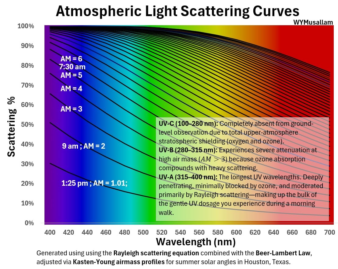
This graph illustrates atmospheric light scattering percentages across the visible light spectrum (400 – 700 nm) as calculated using the Rayleigh scattering equation, the Beer-Lambert law, and Kasten-Young airmass profiles for summer solar angles in Houston, Texas.
It shows a family of curves showing that scattering intensity increases markedly at shorter wavelengths (toward the violet and blue end) and higher air mass values (ranging from AM = 1.01 at 1:25 pm up to AM = 6 at 7:30 am), which causes greater attenuation when the sun is lower on the horizon.
Regarding Ultraviolet light:
- UV-C (100–280 nm): Completely absent from ground-level observation due to total upper-atmosphere stratospheric shielding (oxygen and ozone).
- UV-B (280–315 nm): Experiences severe attenuation at high air mass (AM > 3) because ozone absorption compounds with heavy scattering.
- UV-A (315–400 nm): The longest UV wavelengths. Deeply penetrating, minimally blocked by ozone, and moderated primarily by Rayleigh scattering—making up the bulk of the gentle UV dosage you experience during a morning walk
Appendix 1 – Flux , Exitance (Emittance), Radiance, Irradiance, and Intensity
Light energy can be expressed in different ways.
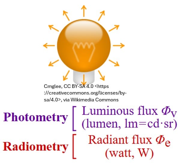
Radiant Flux
Radiant Flux, Φe , is the total power coming off a source in all directions.
Power is Energy/time. Has SI units of Joules/second = Watts = W.
Picture: Radiant Flux
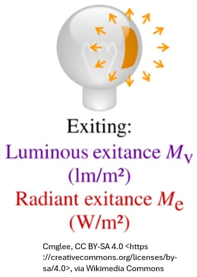
Radiant Exitance (or Emittance)
- It is the total energy leaving a surface in all directions, broken down by wavelength.
- The radiant (luminous) exitance is the energy per unit area leaving a surface.
- Imagine standing back and measuring every single photon flying off a flat glowing plate into the entire hemisphere above it.
- Unit of measure: Power per unit area (W / m²) but can be expressed also per wavelength (W / m² / m).
- It ignores direction; it just asks, “How much total power is pouring out of this patch of surface?”
Picture: Exitance
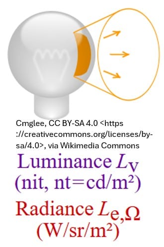
Radiance
- Radiance is the directional view: power leaving a surface per unit area, per solid angle (steradian; see wuz), and per wavelength.
- We could call it the surface radiance also: the surface radiance (luminance) is the intensity per unit area leaving a surface.
- Instead of looking at the whole hemisphere, you zoom in on one specific “dot” on the surface and look at it from one precise angle through a narrow cone of sight.
- Units of measure: W / (m² x sr ) or sometimes expressed per wavelength as W / (m² x sr x m)
- Radiance accounts for geometry and directionality.
Picture: Radiance
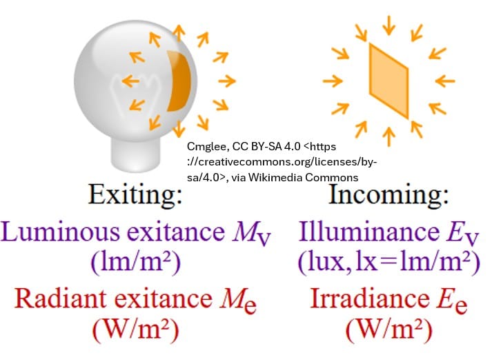
Irradiance: Inverse-Square Law Relationship (I = P / 4π r²)
- This calculates irradiance (or sometimes called flux density), not radiance.
- Be aware that very often engineers and physicists will call this wave intensity or solar intensity which technically is not consistent with common radiometry terms.
- The irradiance (illuminance) is the power per unit area incident on a surface.
- You take the Sun’s total output power (P), and spread it out over the surface area of an expanding imaginary sphere of radius r (4π r²) centered on the Sun.
- When that energy hits Earth, you are calculating how much power is arriving per unit area.
- Units of measure: Power per unit area (W / m²).
Picture: Irradiance
Be Careful When you use the word Intensity
Be aware that people will call P / (4π r²) “wave intensity” or “solar intensity.”
But in strict radiometry terminology,
- power received by a surface is irradiance (Watts/m²),
- while power emitted from a point source per solid angle is radiant intensity (W/sr).